
Application Manual and System Selection Guide


4
4. Square footage of partitions — the walls between a
conditioned and unconditioned area (such as a living
room and attached garage).
5. Square footage of all exposed doors and windows.
6. Square footage of all exposed sliding glass doors.
These are considered “windows” for cooling and “doors”
for heating.
7. Square footage of exposed ceiling in each room. All
rooms in a one-story structure have exposed ceilings.
All second oor rooms in a two-story structure have
exposed ceilings.
8. Square footage of exposed oors or oors over an
unconditioned area in each room.
9. Indicate North-South and East-West directions.
Now, you’re ready to perform the heat gain/lost
calculations using the SpacePak Kwik-Way Heating &
Air Conditioning Sizing Sheet (Form PR108).
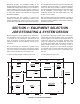
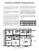
KWIK-WAY EXAMPLE
For our Kwik-Way example, we will use the oor plan
and measurements as shown in Figure 1.2. This will be
a cooling-only installation with the indoor fan coil unit
to be located in a vented attic. Construction consists
of one-story frame over a basement (R-11 insulation
between oor and basement); 3-1/2-inch insulation in
the walls and ceiling; 8-foot ceiling height; double-hung
windows with blinds; storm doors; masonry partition with
no insulation; and inltration (no mechanical ventilation).
There are three occupants, the house faces South and
the summer outdoor temperature is 90°F.
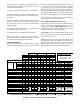
TOTAL STRUCTURE HEAT GAIN (LOSS)
To determine an accurate whole-house heat gain (loss)
for the structure for estimating purposes, you can
complete the TOTAL STRUCTURE column rst on
the Kwik-Way sheet. However, this does not preclude
performing a nal room-by-room analysis.
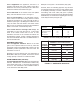
L ft exp wall: At the top of the Kwik-Way sheet, on this
line, ll in the total linear feet of exposed wall for the
structure (see Figure 1.3).
Ceiling Ht: On this line, ll in the ceiling height of the
structure (see Figure 1.3). NOTE: If a room(s) has a
different height than the others, such as one with a
cathedral-type ceiling, then you will have to factor in the
room’s height and linear exposed feet separately.
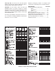
FIGURE 1.3: TOTAL STRUCTURE COOLING EXAMPLE
RECOMMENDED NO. OF OU
ROOM:
X
=
AREA
SQ FT
HEAT
BTU
COOL
BTU
HEAT COOL
TOTAL STRUCTURE
AREA
SQ FT
HEAT
BTU
COOL
BTU
HEAT COOL
FACTORS
HEAT COOL
Lg x Wd
L ft exp wall
Ceiling Ht
To tal Exp wall
ITEM OF CONSTRUCTION
Shade Exposure
N
NE & NW
E & W
SE & SW
S
1 WINDOWS
(cooling)
Including
Glass Doors
2 Glass Doors (heating)
3 Windows (heating)
4 Standard Doors (non-glass)
5 Partitions (less doors & windows)
6 Exposed Walls (less 1, 2, 3, 4 & 5)
7 Ceiling/Roof
8 Floor
9 Ventilation (Mechanical)/Infiltration
10 People
11 Appliances
12 Sub-To tal Lines 1 - 11
13 Sensible {Line 12 x Duct Factor (Fig.1.6)}
14 Heat Gain for Cooling Load (Line 13 x 1.3)
15 Equipment Selected (Fig.1.7)
300
1200
1.3
16 Adjusted Loads: LAF (Fig. 2.3) x Line 13 and Line 14
OUTDOOR UNIT :
ROOM:
X
=
AREA
SQ FT
HEAT
BTU
COOL
BTU
HEAT COOL HEAT COOL HEAT COOL
INDOOR UNIT :
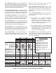
FROM FLOOR PLAN
House Width = 65'
House Depth = 38'
Ceiling Height = 8'
206
8
1648
20
50
25
9
2.3
2.0
2.5
.5
1.2