
Application Manual and System Selection Guide


9
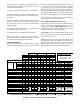
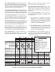
Complete the heat gain (heat loss) for each room
on the Kwik-Way sheet (see Figure 2.1), following
the same procedures you used for calculating the
Total Structure Heat Gain (Loss). Complete each
appropriate calculation through Line 14.
To assure proper balancing of the SpacePak system,
room by room, the next concern is providing each
room in the house with the proper number of air outlets
or room terminators.
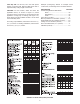
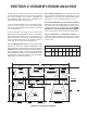
On your oor plan, now “rough in” the location of the
indoor fan coil unit and the plenum duct run. The plenum
duct is normally located in the attic or basement (see
Figure 2.2). Then, estimate the average length (per
room) of supply tubing runs to the outside corners of
each room on your oor plan (see Figure 2.2).
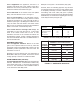
Line 16 Adjusted Loads: Based on the average supply
tubing run for each room, select the appropriate “Length
Adjustment Factor” from Figure 2.3 and enter the factors in
the AREA SQ FT columns for each room. This information
is also available in Table 4 on the back of the Kwik-Way
sheet. Multiply COOL BTU on Line 14 (HEAT BTU on Line
13) by the factors and enter results in column COOL BTU
(HEAT BTU) on Line 16 for each room.
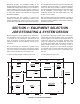
SECTION 2: ROOM-BY-ROOM ANALYSIS
Line 17 Base Load Factors: To obtain the base load
factors, divide the Total Structure COOL BTU on Line
(HEAT BTU on Line 13) by the recommended number
terminators on Line 15 and enter result on Line 17.
Line 18 Recommended No. of Terminators (Outlets):
Divide the COOL BTU (HEAT BTU) for each room or
Line 16 by the cooling (heating) base load factor on Line
17 and enter results on Line 18 for each room. DO NOT
ROUND OFF TO THE NEAREST WHOLE NUMBER -
if less or more than a whole number, leave the fraction.
Line 19 Selected No. of Terminators (Outlets): For
heating installations, select the larger of the two numbers
on Line 18 for each room and enter the results or Line 19
for each room.
FIGURE 2.3: LENGTH ADJUSTMENT FACTORS
2" SUPPLY TUBING LENGTH ADJUSTMENT FACTOR CHART
FACTOR
RUN
1.18 1.14 1.11 1.06 1.0 .9 .8 .66
6' 8' 10' 12'15' 20'25' 30'
DINING ROOM
306 Sq. Ft.
FAMILY
ROOM
216 Sq. Ft.
KITCHEN
198 Sq. Ft.BED. 4
216 Sq. Ft.
BED. 3
180 Sq. Ft.
BED. 2
210 Sq. Ft.
BED. 1
357 Sq. Ft.
LIVING ROOM
580 Sq. Ft.
GARAGE
BATH
126 Sq. Ft.
65'
38'
3'x7'
3'x4' 3'x4'
3'x4'3'x4'3'x4'
3'x4'
3'x4'
3'x4'
3'x4' 5'x4'
5'x4'
3'x7'
3'x7'
8'x4'
18'
12'
12'
15'
14'
15'
21'
17'
7'
18'
18'
17'
18'
12'
18'
20'
29'
7' Partition
18' Partition
N
S
W
E
18' average run
10' average run
11' average run
9' average run
19' average run
19' average run
10' average
run
9' average
run
10' average
run
11'
9'
10'
9'
25'
25'
25'
11'
10'
10'
13'
10'
11'
12'
9'
24'
10'
ESP
Return
Air
FIGURE 2.2: FLOOR PLAN EXAMPLE