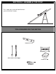
Inground System Owners Manual Customer Service Center • N53 W24700 South Corporate Circle • Sussex, WI 53089 • U.S.A. REQUIRED TOOLS AND MATERIALS: • 2 People • Phillips Screwdriver • Carpenter’s Level • Hammer • WARNING! • Heavy Duty Tape • Container to Mix • 15’ Tape Measure READ AND UNDERSTAND OPERATOR'S MANUAL BEFORE USING THIS UNIT. • Stepladder 8 ft. (2.
BEFORE YOU START! To ensure optimal playability of backboard system, a close tolerance fit between the elevator components and hardware is required. Test-fit large bolts into large holes of elevator tubes, backboard brackets, and triangle plates. Carefully rock them in a circular motion to ream out any excess paint from holes if necessary. Not all items pictured are included with every model.
WARNING Read and understand warnings listed below before using this product. Failure to follow these warnings may result in serious injury and/or property damage. Owner must ensure that all players know and follow these rules for safe operation of the system. • DO NOT HANG on the rim or any part of the system including backboard, support braces or net. • During play, especially when performing dunk type activities, keep player's face away from the backboard, rim and net.
SAFETY INSTRUCTIONS FAILURE TO FOLLOW THESE SAFETY INSTRUCTIONS MAY RESULT IN SERIOUS INJURY, PROPERTY DAMAGE AND WILL VOID WARRANTY. Owner must ensure that all players know and follow these rules for safe operation of the system. To ensure safety, do not attempt to assemble this system without following the instructions carefully. Proper and complete assembly, use and supervision is essential for proper operation and to reduce the risk of accident or injury.
NOTICE TO ASSEMBLERS ALL Basketball Systems, including those used for DISPLAYS, MUST be assembled and ballasted with sand, water or concrete according to the instructions. Failure to follow instructions could result in SERIOUS INJURY. It is NOT acceptable to devise a makeshift weight system. IMPORTANT! Remove all contents from boxes. Be sure to check inside pole sections; hardware and additional parts are packed inside.
PARTS LIST - See Hardware Identifier Item Qty. Part No.
HARDWARE IDENTIFIER (BOLTS & SCREWS) #21 (1) #7 (2) #31 (4) #15 (1)* 204961 hex head bolt 3/8-16 x 5/8 #20 (2) #9 (4) #47 (4) #42 (1) HARDWARE IDENTIFIER (NUTS & WASHERS) #27 (6) #8 (9)* #11 (4) #24 (6) #10 (4) #46 (1) #45 (1) HARDWARE IDENTIFIER (METAL SPACERS) #13 (2) * You may have extra parts with this model.
HARDWARE IDENTIFIER (PLASTIC SPACERS & CLIPS) #22 (4) #12 (2) #23 (4) #39 (2) HARDWARE IDENTIFIER (OTHER) #41 (1) #43 (1) #44 (1) ID# M881111 12/05 8
SECTION A: ASSEMBLE THE POLE This is what your system will look like when you’ve finished this section: TOOLS REQUIRED FOR THIS SECTION CONCRETE Carpenter's Level Shovel and Post Hole Digger Container to Mix Phillips-Head Screwdriver 9 12/05 ID# M881111
1. Correctly identify each pole section. Identification Sticker 1 TOP 2 MIDDLE Identification Sticker 3 BOTTOM 2. Ensure ground is level with playing surface, then dig pole hole. WARNING! IMPORTANT! Maximum distance from edge of hole to edge of playing surface 6” (15.2 cm). CONTACT UTILITIES BEFORE DIGGING. XG02.EPS 18" (42.7 cm) 6" (15.
3. Snap two halves of ground sleeve (4) together. Insert and secure bottom pole section (3) into ground sleeve (4) by tightening ground sleeve cap (5). 3 NOTE: Flared end goes inside ground sleeve. 4 5 4 4 4. Fill hole approximately 1/3 full with mixed concrete.
1" (2.54 cm) 5. FIG. A Insert ground sleeve assembly and center in hole (FIG. A). NOTE: Leave 1" below flange exposed for drainage hill. IMPORTANT! NOTE POSITION OF FLANGE. SIDE VIEW PLAYING SURFACE FLANGE 1" (2.54 cm) IMPORTANT! CONTINUE ON TO NEXT STEP. ID# M881111 12/05 12 DO NOT WAIT FOR CONCRETE TO CURE.
6. Fill hole completely with concrete. 3 1" (2.54 cm) 1" (2.54 cm) 5 4 IMPORTANT! 7. CONTINUE ON TO NEXT STEP. DO NOT WAIT FOR CONCRETE TO CURE. Tamp down concrete to release air pockets and build drainage hill. Level pole section in all directions several times while concrete is curing. NOTE: 1" (2.54 cm) DRAINAGE HILL Make a reference mark here for antiskid tape. 1" (2.54 cm) NOTE: PLAYING SURFACE 1" (2.54 cm) Keep flange pushed down to concrete and leveled.
8. After concrete has cured, remove bottom pole section from ground sleeve (4). Place antiskid tape (36) around the bottom area of bottom pole (see note A). NOTE A: Place top edge of antiskid tape on mark made in step 7, NOTE A. NOTE B: Tape prevents the pole from rotating during play. 36 5 4 IMPORTANT! KEEP GROUND SLEEVE CAP ON BOTTOM POLE.
9. Stack and bounce bottom (3) and middle (2) pole sections together. Bounce pole sections together until middle section no longer moves toward taped reference mark on bottom pole. IMPORTANT! 5" (12.7 cm) BOTTOM POLE 1-1/2" (3.81 cm) POLE SECTIONS SHOULD HAVE A 3-1/2" (9 CM) MINIMUM OVERLAP. 2 BOTTOM POLE Identification Sticker IMPORTANT! 5 3 KEEP GROUND SLEEVE CAP ON BOTTOM POLE.
10. Stack upper pole section (1) to bottom and middle pole assembly and continue bouncing until top pole (1) no longer moves toward taped reference mark on middle pole. IMPORTANT! WARNING FAILURE TO IN SERIOUSFOLLOW THESE INJURY WARNINGS AND/OR Owner PROPERTYMAY RESULT must DAMAGE. these ensure that rules for safe all players • DO NOT operation know and follow of the includingHANG on the system. • During backboard, rim or any part play, activities, especiallysupport braces of the system or net. and net.
11. Install pole mount bracket (6) and bracket reinforcement (40) with carriage bolts (7) as shown. Tighten flange nuts (8) completely.
Attach spacers (12, 13) to pole mount bracket (6) with bolts (9), washers (10), and nuts (11) as shown. 12. 6 10 IMPORTANT!: 10 11 Tighten just until washers (10) stop moving. 13 12 9 13 12 Assemble lanyard (17) to locking pin (16) as shown. Attach covers (14) onto pole mount bracket (6) with carriage bolt (15) and nut (8) as shown. 13. IMPORTANT! Loop end of pin lanyard (17) over carriage bolt (15) as it passes through the pole mount bracket (6) during this assembly.
14. 15. Apply logo and height indicator labels (19) to adjustment rod (18) as shown. Attach handle parts (37, 38) to adjustment rod with screw (21), carriage bolt (20), and flange nut (8) as shown. SIDE ACCESS Insert handle assembly through pole mount assembly as shown. Lock pole assembly in place at the 10’ (3.05 m) mark with pin (16). NOTE: Holes in adjustment rod allow for either rear access or side access.
SECTION B: ASSEMBLE THE ELEVATOR TUBES TO BACKBOARD This is what your system will look like when you’ve finished this section. TOOLS REQUIRED FOR THIS SECTION (2) Socket Wrenches and Sockets (2) 1/2”, (2) 9/16”, and 2 3/4” Wrenches AND/OR 1/2” 9/16” 3/4” 1. Identify elevator tubes (28 & 30).
1. Attach backboard support brackets (25) to the backboard frame using bolts (31) and nuts (10) as shown. 11 IMPORTANT! 11 31 25 31 IMPORTANT! 25 DO NOT TIGHTEN HARDWARE COMPLETELY. IMPORTANT! 25 NOTE ORIENTATION.
2. Attach lower elevator tubes (28) and springs (29) to backboard support brackets (25) using spacers (22), bolt (27), and nut (24) as shown. Insert T-bolt (42) into Slam Jam bracket (41) then, attach that assembly to board using bolts (47) and nuts (8).
3. Attach upper elevator tubes (30) to backboard support brackets (25) using spacers (22), bolt (27), and nut (24) as shown.
SECTION C: ATTACH THE BACKBOARD & ELEVATOR ASSEMBLY TO POLE SYSTEM This is what your system will look like when you’ve finished this section: CONCRETE TOOLS REQUIRED FOR THIS SECTION Container to Mix AND/OR 3/4” (2) Socket Wrenches and Sockets (2) 3/4" Wrenches ID# M881111 12/05 24
1. Support pole on sawhorse. Attach backboard assembly to top pole section (1). 24 24 WARNING! 30 USE CAUTION; ELEVATOR ASSEMBLY IS HEAVY. 28 TWO PEOPLE REQUIRED FOR THIS PROCEDURE. FAILURE TO FOLLOW THIS WARNING COULD RESULT IN SERIOUS INJURY AND/OR PROPERTY DAMAGE. 23 1 23 23 23 30 28 27 27 2. Install handle assembly to long elevator tubes (28) using bolt (27), spacers (39), and nut (24) as shown. 39 24 NOTE: Before going on to next step, adjust system assembly to the 10’ setting.
3. Install Slam Jam Rim to Backboard A • B • Fit rim (32) securely into bracket (41) as shown (Allow "T"-bolt (42) to slip through center hole in rim (32). Install reinforcement bracket (43) onto “T” bolt (42) as shown. C • Install spring (44) onto “T” bolt (42) as shown. D • Install special nut (46) and washer (45) onto “T” bolt (42). E • Tighten nut (46) until flush with end of “T” bolt (42).
5. Insert bolt (27) through left side short elevator tube (30), then stretch spring or springs (29) onto bolt (27). Insert bolt (27) through right side short elevator tube (30) and secure with nut (24). WARNING! USE EYE PROTECTION WHEN INSTALLING SPRINGS.
6. Assemble rebar centering spacers (49) near top and bottom of rebar (48) as shown. 7. Place rebar with spacers into bottom pole section (3) as shown. 49 2" 48 49 3 48 49 3" 8. Reinforcement Bar Seal hole at the bottom of the bottom pole with heavy-duty tape (not included) to retain rebar and concrete inside.
9. Fill pole with concrete approximately 1” (2.54 cm) below bottom elevator hole as shown. 1 IMPORTANT!: FAILURE TO FILL YOUR POLE COMPLETELY WITH CONCRETE AS DESCRIBED IN THESE INSTRUCTIONS WILL VOID ALL WARRANTIES WRITTEN AND IMPLIED. IMPORTANT!: Make sure that concrete does not bulge from the end of pole assembly. Allow concrete to completely cure. IMPORTANT!: WAIT A MINIMUM OF 24 HOURS BEFORE GOING ON TO NEXT STEP. CONCRETE MUST CURE. 10. Install net (34). B. A. 34 D. C.
SECTION D: UPRIGHT, SECURE AND USE POLE SYSTEM This is what your system will look like when you’ve finished this section.
1. After concrete has cured, remove tape, install pole cap (26), fit pole assembly into sleeve (4). 10ft (3.05 m) WARNING! TWO PEOPLE REQUIRED FOR THIS PROCEDURE. FAILURE TO FOLLOW THIS WARNING COULD RESULT IN SERIOUS INJURY AND/OR PROPERTY DAMAGE. WARNING! 26 DO NOT USE THE BACKBOARD OR RIM TO MOVE POLE ASSEMBLY INTO POSITION. THE BACKBOARD AND RIM ARE NOT LOCKED AND WILL ROTATE. FAILURE TO FOLLOW THIS WARNING COULD RESULT IN SERIOUS INJURY AND/OR PROPERTY DAMAGE. 4 PLAYING S URFACE 2.
3. A. While holding handle, remove pin (16). B. Move elevator up or down to desired height. C. Replace pin (16) full length to lock system at desired height. 4. Apply height adjustment label (35) to front of pole as shown. Regulation rim height is 10 feet (3.05 m). WARNING! DO NOT ALLOW CHILDREN TO ADJUST HEIGHT. 35 Si Co 10 ft. (3.05 m) Di HEIGHT ADJUSTMENT 3. Al 1 1 TO ADJUST BACKBOARD: 3 1. While holding handle, remove pin. 2. Move elevator up or down to desired height. 2 2 B.