Span Panel Installation Manual for 2nd Generation models (1-00800-xx) WWW.SPAN.
All installations must conform to the laws, regulations, codes and standards applicable in the jurisdiction of installation. Before starting an installation, consult a local building or electrical All specifications and descriptions contained in this document are accurate at the time of inspector for current requirements. Local codes may vary but are adopted and enforced to publication. In the interest of product improvement, Span reserves the right to make product promote safe electrical installations.
CONTENTS ABOUT YOUR SPAN PANEL PREPARING TO INSTALL 1. Unpacking and Inspecting the Panel 2. Installation Requirements 3. Planning the Install Location INSTALLATION 1. Mounting the Panel 2. Using the Panel as Service Equipment 3. Selecting Breakers 4. Wiring the Panel 5. Communication Wiring 6. Configuring the Door Swing Direction 7. Installing the Flush Mount Trim Kit 8. Final Inspection and Closing the Unit 9.
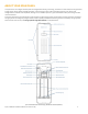
ABOUT YOUR SPAN PANEL The Span Panel is an intelligent breaker panel with integrated connectivity, monitoring, and control for home loads, solar PV generation, energy storage, electric vehicle charging equipment, and the utility grid. Span is wall-mounted and similar in size, weight, and configuration to traditional electrical panels, allowing it to be installed in place of a typical 120/240VAC breaker panel using standard tools and materials.
PREPARING TO INSTALL 1. Unpacking and Inspecting the Panel Inspect the packaging and Span Panel for damage.
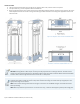
3. Planning the Install Location Electrical, Mechanical, and Environmental Requirements ● ● ● The Span Panel is service entrance rated. When used as service equipment, primary overcurrent protection for the site is required in the form of an installed main breaker not to exceed 200 A. The Span Panel is intended to be wall-mounted between studs (2x4’ or equivalent) with 16-inch spacing, using all 4 mounting points.
Accessories The following accessories may be used with Span Panels: Part Manufacturer Part Number Span Flush Mount Trim Kit Span PN: 1-01046 Span Networking Kit (for multi-panel sites) Span PN: 1-00921 Service entrance barrier cover SquareD PN: PKSB1HA Top hub closing plate SquareD PN: ACPCP Top threaded conduit hub, rainproof SquareD A series hubs Filler plate for branch breaker knockouts SquareD PN: HOMFPCP Add-on Neutral / GND lugs (Field-installed) Siemens ECLK2 Siemens ECLK3 Eaton NL30
INSTALLATION 1. Mounting the Panel Remove the Deadfront ● Using a flat screwdriver, loosen the single deadfront fastener screw and remove the deadfront cover. Mount the Unit ● ● ● Ensure the wall space can accommodate the flush section without interference from pipes or conductors inside the wall space. Using a drill and level, mount the Span Panel enclosure on the wall, observing site and mechanical requirements, and applicable building codes. Secure the unit at all 4 mounting points.
Install Conduit ● ● ● The Span Panel allows conduit entry through the top, bottom, lower sides, and rear section of the panel. For top conduit entry, install a SquareD A-series threaded hub. Before removing knockouts, plan conduit routes and corresponding knockout locations and sizes on the enclosure. Be sure to allow adequate clearance for conduit routing and anchoring. Conduit installation must comply with applicable fill limits and electrical codes.
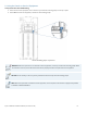
2. Using the Panel as Service Equipment Verify Neutral-to-Ground Bonding ● ● When used as service equipment, ensure the factory-installed main bonding jumper is securely in place. When not used as service equipment, remove the main bonding jumper. Location of bonding jumper in Span Panel WARNING: When the Span Panel is not installed as service equipment, the factory-installed main bonding jumper MUST be removed.
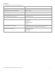
3. Selecting Breakers ● ● The Span Panel accepts a 100–200 A main breaker and up to 32 branch breakers in the panel for load circuits. Install each branch breaker by rocking it down to seat it fully onto the busbar stab and engaging the clips that hold it in position. Ensure each breaker is firmly in place. CAUTION: Install only listed and labeled circuit breakers compatible with the Span Panel. Branch circuits must not exceed the load limits specified below.
Replacing the Main Breaker • • • • • Remove the two (2) main breaker fastening nuts using a 7/16-inch hex socket. Remove the fastening screw using a #2 Philips bit. Slide the main breaker downwards and remove, then insert the new main breaker (see table above for acceptable models). Replace the fastening screw, torquing to 31 in-lbs (3.5 N-m). Replace the two (2) fastening nuts, torquing to 45 in-lbs (5.1 N-m) using a 7/16-inch hex socket.
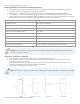
4. Wiring the Panel Size all conductors with reference to the overcurrent protection device, ampacity, and voltage drop requirements in accordance with all local electrical codes. Use conductors rated to minimum of 75°C. ● ● ● ● Connect supply-side Line 1 and Line 2 conductors to the main breaker terminals. Connect supply Neutral and Ground conductors to their respective terminal blocks. Refer to the table below for suitable conductor gauges and torque requirements.
Terminal Wire Gauge, Strip Lengths, and Torque Values Terminal name Wire gauge (AWG) Wire strip length Tool Torque value in-lbs (Nm) A Main Breaker B Main Neutral & Main GND terminal #6 - 250 kcmil 1.25 in (32 mm) 3/8-in hex 250 - 275 (28.2 - 31.1) C Larger Neutral terminals #14 - 1/0 0.75 in (20 mm) 5 mm slotted 35 (4.0) for #14-10 40 (4.5 ) for #8 45 (5.1) for #6-4 50 (5.6) for #3-1/0 D Smaller Neutral terminals & GND terminal block #14 - 4 0.5 in (12 mm) 5 mm slotted 20 (2.
5. Communication Wiring ● ● Use minimum 300 V rated, shielded, twisted-pair, copper conductors only for communication wiring. Connecting the Span Panel to the Internet with a wired Ethernet is strongly recommended. NOTE: To insert wiring into RS485 terminal, use a 2mm flat head driver to depress the tab while inserting stripped wire. Span 1-00800-xx Installation Manual (rev.
6. Configuring the Door Swing Direction To configure the door to open from the other direction: ● ● ● Using a #2 Philips driver, remove the 2 hinge brackets and 2 latch brackets from the enclosure. Re-install the hinge and latch brackets on the desired side, tightening each screw (2 per bracket) and torque to 26.5 in-lbs (3 Nm). On the inside of the door, remove and swap the mating hinge and latch hardware, and re-install and torque to 26.5 in-lbs (3 Nm).
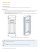
7. Installing the Flush Mount Trim Kit The Flush Mount Trim Kit (PN: 1-01046) is used for indoor installations to easily cover square holes cut into the wall during installation. The overall dimensions when mounted are 1123 x 405 mm (44.2 x 15.9 in). • • • Place the two (2) metal Trim Mounting Brackets directly against the Span Panel’s top and bottom faces, using the triangular decals to center. Affix the upper and lower Trim Mounting Brackets to the wall or stud using four (4) mounting screws.
8. Final Inspection and Closing the Unit ● ● ● ● ● Confirm that all connections are correct, properly grounded, and secure. Replace the deadfront and securing using the flathead screw. Install the door by sliding down onto the hinges. Only after fully replacing the deadfront assembly, restore power. Lock the panel closed with the hasp at the bottom of the panel door using a lock provided by the homeowner. WARNING: Risk of electric shock.
TROUBLESHOOTING & SERVICING For additional troubleshooting and support visit www.support.span.io Communication with the Span Panel Follow these troubleshooting steps to establish communication and verify operation of the Span Installer App: ● ● ● ● ● Wait at least 3 minutes after powering on before attempting to connect to the Panel. Ensure the panel is connected to the internet, using the Installer App. Ensure the battery backup system is communicating with the Span Panel using the Installer App.
Resetting the System If it becomes necessary to restart the system use a small tool to press the Reset button, located below the communication terminals. Hold the button for 10 full seconds before releasing. Overriding the Grid Disconnect Relay If it is necessary to manually reconnect your home to the grid, Span Support may direct you to operate the manual override in the Span Panel.
APPENDIX A: CIRCUIT BREAKER COMPATIBILITY Span has been evaluated per the UL Standard for Panelboards for use with the branch breaker types below. Informational notes: • • National Electric Code (NFPA 70) does not prohibit the use of different branch circuit breakers in panelboards provided it does not violate the listing of any equipment. NEC article 110.
• • • • • • Branch-feeder arc fault circuit interrupter circuit breakers type QAF2; 1-pole and 2-pole; rated 15-20 amperes; catalog numbers QA followed by 115 to 120; followed by AF; may be followed by H. Combination arc fault circuit interrupter circuit breakers type QAF and QAF2; 1-pole and 2-pole; rated 10-20 amperes; catalog numbers Q or QA followed by 110 to 220; followed by AFC; may be followed by H.
APPENDIX B: SURGE PROTECTIVE DEVICE COMPATABILITY Per 2020 NEC 230.67 Surge Protection • • • A surge protective device (SPD) shall be installed in all new and replacement services supplying dwelling units. Shall be Type 1 or Type 2 SPD. Shall be attached to the service equipment or immediately adjacent. Exception: The SPD shall not be required to be in the service equipment if located at each next level distribution equipment downstream toward the load.
Revision Log Version Note 2021-05-15 ● First revision 2021-06-04 ● ● ● Corrected product weight in spec table Added Networking Kit and Trim Kit to accessory list Added Servicing instructions regarding breaker replacement or additions 2021-06-21 ● ● Added main breaker replacement details Added Flush Mount Trim Kit installation instructions 2021-06-29 ● Added dimensions for Flush Mount Trim Kit 2021-12-04 ● Added Appendix A: Circuit Breaker Compatibility 2022-01-21 ● ● ● Added Appendix B: S