SPAN Drive Installation Manual Version 1.
Product Specifications All specifications and descriptions contained in this document are accurate at the time of publication. In the interest of product improvement, SPAN reserves the right to make product modifications at any time without advance notice. For the latest SPAN product and installation documents, visit: www.SPAN.io/partner-portal For errors or omissions, contact support@SPAN.
Contents About your SPAN Drive 4 SPAN Drive Datasheet 5 Preparing to install 6 1. SPAN Drive Package Contents 6 2. Installation Requirements 7 Required Equipment Required Tools 3. Planning the Install Location 8 Electrical, Mechanical, & Environmental Requirements Dimensions, Clearances, and Access Installation 10 1. Determine Wiring Entry 10 2.
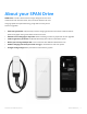
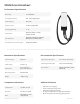
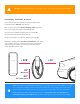
About your SPAN Drive SPAN Drive is the first level 2 vehicle charger designed for real-time coordination with all home loads, solar, and home batteries for max charging speeds and optimized energy usage without costly home electrical upgrades.
SPAN Drive Datasheet Performance Specifications Max Power 11.52 kW (48 A) AC Voltage (Nominal) 208 - 240 V single-phase Grid Frequency 50 / 60 Hz Output Current 6 - 48 A (configurable) AC Energy Metering +/- 1% Connectivity Ethernet, WiFi (2.5, 5 GHz), Cellular (4G/LTE) User Interfaces SPAN Home App (iOS, Android)1, Onboard status illumination Ground Fault Circuit Interrupter Integrated (CCID20) 1. When paired with a SPAN Panel.
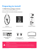
Preparing to install 1. SPAN Drive package contents Inspect the packaging and SPAN Drive for damage. Ensure you have received the following components: SPAN Drive (with charging cable attached) Getting Started Card Installation template 1X Buttonhead screw & 1X Flathead (extra for charger assembly) Optional gasket (for rear entry installation) Included mounting parts: 3X #12 Phillips screw & anchors WARNING: If the unit is damaged in any way, do not proceed with the installation.
2. Installation requirements You will also need the following equipment and tools that are not included in the packaging: Required equipment Required tools • • • • • • • • Copper conductors rated to a minimum of 90°C, such as THHN, THWN, NM-B, MC. Cable for communication between SPAN Drive and the SPAN Panel (Minimum 300 V rated, shielded, twisted-pair, 24–16 AWG). RS485-G optional, but recommended to connect Drain wire to Drive and Panel RS485-G terminals for best signal integrity.
NOTE: Verify that the site mechanical, electrical, and clearance requirements outlined in this document and the product datasheet are compatible at the planned installation location. NOTE: NEMA 3R rated conduit fittings are required for outdoor installations. 3. Planning the install location Electrical, Mechanical, & Environmental Requirements Before beginning work, check the site for appropriate mounting location and electrical capacity. The environmental rating of Drive is identical to that of the Panel.
CAUTION: Follow all local codes and standards when planning for and installing SPAN Drive. Dimensions, clearances, & access The maximum distance SPAN Drive can be installed from the SPAN Panel is 328 feet (100 meters). Pick a location where the 20-foot charging cable will reach the car’s charging port while still providing slack. The minimum installation height must be at least 18”, measured from the bottom of the charger. SPAN recommends an installation height of at least 40”.
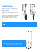
Installation 1. Determine wiring entry Bottom or rear entry SPAN Drive allows power supply wiring and conduit entry either through the bottom or rear section of the charger. Before proceeding with the hardwire installation, determine the most appropriate entry location based on the placement of wiring or conduit. Be sure to note that the bottom and rear entry locations are both on the left side of the charger.
2. Placement & preparing Remove the glass and lower plastic covers 1. Using a #2 Phillips screwdriver, remove the single fastener on the top surface of Drive (where the charging cable nests). Then, pull the top of the glass cover away from the charger to remove. 2. Using a #2 Phillips screwdriver again, remove the bottommost screw and loosen the 4 Phillips screws on the front face of SPAN Drive. Then, take off the lower plastic cover. Set the covers aside.
Preparing conduit fittings & bushings The default conduit size is ¾” (21mm). 1” (27mm) conduit is acceptable if needed. Based on fittings and conduit size, prepare SPAN Drive: For bottom entry, manually remove the conduit plug. For rear entry, drill with a step bit to prepare SPAN Drive for fittings. The knockout size is ¾” trade size and can also accommodate 1” trade size. 3. Mounting SPAN Drive Depending on the material of the mounting wall, use the appropriate hardware and drill pilot holes as needed.
4. Electrical wiring AC Power Wiring Insert the AC power conductors either through the bottom or rear entry opening in SPAN Drive. Ensure there’s enough length for a 6” service loop in the enclosure, as well as to easily connect the wires into the lever lock terminal. If using a conduit connection, pull the wiring through before connecting the conduit. Use appropriate cable glands, bushings, or fittings to secure the wiring in place and protect from water and debris.
Communication wiring Connect the communication wires according to the diagram below. Use minimum 300 V rated, 24–16 AWG, shielded, twisted-pair, copper conductors only for communication wiring. Strip 3/8” (10mm) of insulation off each wire and fully insert into the terminal. RS485-G optional, but recommended to connect Drain wire to Drive and Panel RS485-G terminals for best signal integrity. When only installing one SPAN Drive, leave the terminating resistor as is.
5. Rated current adjustment On the left side of the circuit board, locate the current selector switch, and set the switch to the appropriate setting per the chart below. If installing with a SPAN Panel, the current selector switch can be left at “0”, and the current rating can be set through the SPAN Installer App.
6. Connection to SPAN Panel WARNING: Risk of electric shock. Make sure power is turned off while connecting SPAN Drive to the SPAN Panel. Always make sure all electrical equipment is safely de-energized before beginning work. WARNING: Ensure all power and ground connections, especially those at the breaker and bus bar, are clean and tight. Remove all oxide from all conductors and terminals before connecting wiring. • • • Ensure that the breaker in SPAN is turned off.
7. Final inspection & closing the unit Confirm that all connections are correct, properly grounded, and secure. Reassemble SPAN Drive by attaching the lower plastic cover and glass cover back onto the device using a #2 Phillips screwdriver. Do not over-tighten the screws. Drape the charging cable around your charger and dock your EV connector in the holster. Only after fully replacing the lower plastic cover and glass cover, restore power. 8.
Troubleshooting & servicing For additional troubleshooting and support visit www.support.span.io or contact SPAN customer service at (415) 286-5252. WARNING: Do not attempt to open, disassemble, repair, tamper with, or modify the equipment. The equipment contains no user-serviceable parts. Contact the installer who installed the equipment for any repairs. Only qualified electrical personnel should open SPAN Drive.
Revision Log Version Note 2022-06-03 First revision SPAN Drive Installation Manual Troubleshooting & Servicing | 19