
Data Sheet
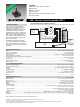


Features
■ Absolute encoder / absolute code output
■ Digital output
■ Sturdy construction
■ Bushing mount
■ Available with PC board mounting bracket (optional)
■ *RoHS compliant
EAW - Absolute Contacting Encoder (ACE
™
)
*RoHS Directive 2002/95/EC Jan. 27, 2003 including annex and RoHS Recast 2011/65/EU June 8, 2011.
Specifi cations are subject to change without notice.
The device characteristics and parameters in this data sheet can and do vary in different applications and actual device performance may vary over time.
Users should verify actual device performance in their specifi c applications.
Electrical Characteristics
Output ...............................................................................................................................................................................8-bit code with 128 absolute states
Closed Circuit Resistance ...........................................................................................................................................................................5 ohms maximum
Open Circuit Resistance ....................................................................................................................................................................... 100 K ohms minimum
Contact Rating .................................................................................................................................................. 10 milliamp @ 10 VDC or 0.1 watt maximum
Insulation Resistance (500 VDC) ...................................................................................................................................................1,000 megohms minimum
Dielectric Withstanding Voltage (MIL-STD-202 Method 301)
Sea Level ............................................................................................................................................................................................ 1,000 VAC minimum
Electrical Travel .....................................................................................................................................................................................................Continuous
Contact Bounce (60 RPM)........................................................................................................................................................... 2.7 milliseconds maximum*
RPM (Operating) .............................................................................................................................................................................................. 120 maximum
Environmental Characteristics
Operating Temperature Range .......................................................................................................................................-40 ºC to +85 ºC (-40 °F to +185 °F)
Storage Temperature Range ..........................................................................................................................................-40 ºC to +85 ºC (-40 °F to +185 °F)
Humidity................................................................................................................................................................. MIL-STD-202, Method 103B, Condition B
Vibration .......................................................................................................................................................................................................................... 15 G
Contact Bounce ...........................................................................................................................................................................0.1 millisecond maximum
Shock............................................................................................................................................................................................................................... 50 G
Contact Bounce ...........................................................................................................................................................................0.1 millisecond maximum
Rotational Life.................................................................................................................................................................... 50,000 shaft revolutions minimum
IP Rating ..........................................................................................................................................................................................................................IP 40
Mechanical Characteristics
Mechanical Angle ........................................................................................................................................................................................ 360 ° Continuous
Running Torque .............................................................................................................................................................. 0.5 to 1.5 N-cm (0.75 to 2.50 oz-in.)
Mounting Torque .........................................................................................................................................................................79 N-cm (7 lb.-in.) maximum
Shaft Side Load (Static)....................................................................................................................................................................4.5 kg (10 lbs.) minimum
Weight ................................................................................................................................................................................ Approximately 14 gms. (0.50 oz.)
Terminals ................................................................................................................................................................................. Printed circuit board terminals
Soldering Condition
Manual Soldering ................................................................................................................... 96.5Sn/3.0Ag/0.5Cu solid wire or no-clean rosin cored wire
370 °C (700 °F) max. for 3 seconds
Wave Soldering ...........................................................................................................................................96.5Sn/3.0Ag/0.5Cu solder with no-clean fl ux
260 °C (500 °F) max. for 5 seconds
Wash processes .................................................................................................................................................................................... Not recommended
Marking ...........................................................................................................................Manufacturer’s name and trademark, part number, and date code.
Hardware ................................................. One lockwasher and one mounting nut are shipped with each encoder, except where noted in the part number.
Packaging ............................................................................................................................................................................................................. 45 pcs./tray
*High probability of missing quadrature codes with maximum bounce.
General Information
*RoHS COMPLIANT
Until now, the choice of an absolute
encoder meant an expensive, and larger-
sized product. Through the use of
combinatorial mathematics, the absolute
code pattern of the Bourns
®
Absolute
Contacting Encoder (ACE
™
) is placed on a
single track for a very economical, energy-
effi cient and compact product. Bourns
®
ACE
™
provides an absolute digital output
that will also retain its last position in the
event of a power failure.
An intelligent alternative to incremental
encoders and potentiometers, the Bourns
®
ACE
™
is ideally suited for many industrial,
automotive, medical and consumer product
applications.
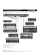
Recommended Control Diagram for ACE-128
P8
1
μP
RESNET
4609X-
101-472
“common” is either
on a decoded
“select” pin
(active low)
or at GND.
ACETAB:
256 byte
code
conversion
table (ROM)
P7P6P5P4P3P2P1
2
C
3
4
8
7
C
6
5