
Data Sheet


Startup Startof
Conversion
Delay
(1)
NOTE:(1)DelayissetbyCR1andCR0.
26ms
26ms
Measured
Temperature
T
HIGH
T
LOW
TMP102 ALERTPIN
(ComparatorMode)
POL=0
TMP102 ALERTPIN
(InterruptMode)
POL=0
TMP102 ALERTPIN
(ComparatorMode)
POL=1
TMP102 ALERTPIN
(InterruptMode)
POL=1
Read Read
Time
Read
SHUTDOWN MODE (SD)
FAULT QUEUE (F1/F0)
THERMOSTAT MODE (TM)
POLARITY (POL)
TMP102
SBOS397B – AUGUST 2007 – REVISED OCTOBER 2008 ...............................................................................................................................................
www.ti.com
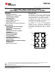
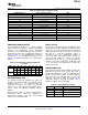
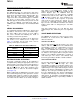
After power-up or general-call reset, the TMP102
immediately starts a conversion, as shown in
Figure 9 . The first result is available after 26ms
(typical). The active quiescent current during
conversion is 40 µ A (typical at +27 ° C). The quiescent
current during delay is 2.2 µ A (typical at +27 ° C).
Figure 9. Conversion Start
The Shutdown mode bit saves maximum power by
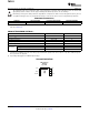
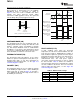
Figure 10. Output Transfer Function Diagrams
shutting down all device circuitry other than the serial
interface, reducing current consumption to typically
less than 0.5 µ A. Shutdown mode is enabled when
the SD bit is '1'; the device shuts down when current
A fault condition exists when the measured
conversion is completed. When SD is equal to '0', the
temperature exceeds the user-defined limits set in the
device maintains a continuous conversion state.
T
HIGH
and T
LOW
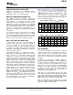
registers. Additionally, the number of
fault conditions required to generate an alert may be
programmed using the fault queue. The fault queue is
The Thermostat mode bit indicates to the device
provided to prevent a false alert as a result of
whether to operate in Comparator mode (TM = 0) or
environmental noise. The fault queue requires
Interrupt mode (TM = 1). For more information on
consecutive fault measurements in order to trigger
comparator and interrupt modes, see the High- and
the alert function. Table 9 defines the number of
Low-Limit Registers section.
measured faults that may be programmed to trigger
an alert condition in the device. For T
HIGH
and T
LOW
register format and byte order, see the High- and
Low-Limit Registers section.
The Polarity bit allows the user to adjust the polarity
of the ALERT pin output. If POL = 0, the ALERT pin
Table 9. TMP102 Fault Settings
will be active low, as shown in Figure 10 . For POL =
F1 F0 CONSECUTIVE FAULTS
1, the ALERT pin will be active high, and the state of
the ALERT pin is inverted.
0 0 1
0 1 2
1 0 4
1 1 6
8 Submit Documentation Feedback Copyright © 2007 – 2008, Texas Instruments Incorporated
Product Folder Link(s): TMP102