
Guide


3/7/2018 SparkFun Inventor's Kit for micro:bit Experiment Guide - learn.sparkfun.com
https://learn.sparkfun.com/tutorials/sparkfun-inventors-kit-for-microbit-experiment-guide/all#introduction-to-microsoft-makecode 39/63
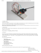
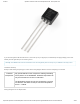
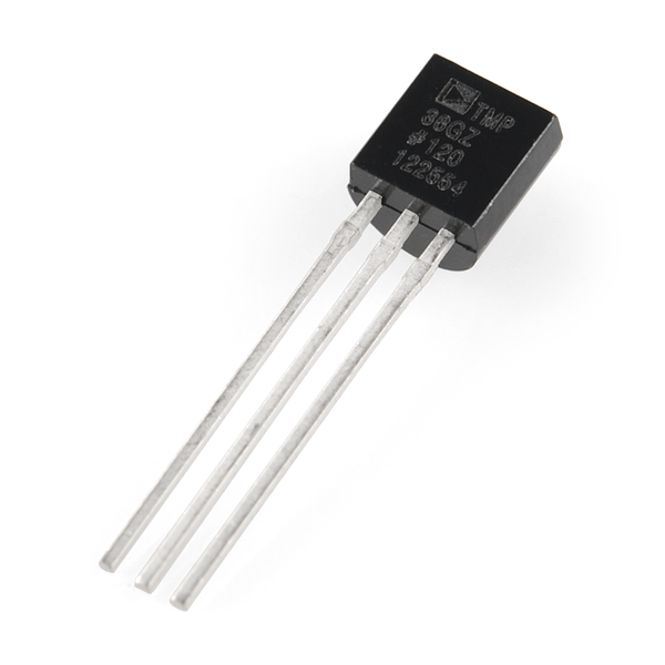
If you are looking at the flat face with text on it, the center pin is your signal pin, the left-hand pin is supply voltage (3.3V in this
tutorial), and the right-hand pin connects to ground.
Pro Tip: The TMP36 looks a lot like a transistor. Put a dot of fingernail polish on the top of your TMP36 so it’s easy to find.
Hardware Hookup
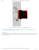
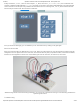
Ready to start hooking everything up? Check out the wiring diagram below to see how everything is connected.
Polarized
Components
Pay special attention to the component’s markings indicating
how to place it on the breadboard. Polarized components can
only be connected to a circuit in one direction.
The temperature sensor can only be connected to a circuit in
one direction. See below for the pin outs of the temperature
sensor --- TMP36.
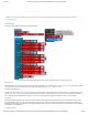
Wiring Diagram for the Experiment