ID-2/12/20 LA Series Datasheet X1 11.04.2013 ID-2LA, ID-12LA, ID-20LA Low Voltage Series Reader Modules Datasheet Version1.0 Date 09/01/13 www.id-innovations.
ID-2/12/20 LA Series Datasheet X1 11.04.2013 Content 1. Overview .......................................................................................................................................3 2. Pin Out for ID12-LA and ID20-LA .....................................................................................................3 ID-12LA, ID-20LA.........................................................................................................................3 ID-2LA ......................
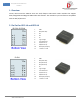
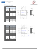
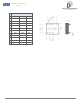
ID-2/12/20 LA Series Datasheet X1 11.04.2013 1. Overview ID2-LA, ID12-LA and the ID20-LA series are small footprint 2.8-5.0volt reader modules that support ASCII, Wiegand26 and Magnetic ABA Track2 data formats. The modules are pin and function compatible with the ID2/12/20 series. 2. Pin Out for ID12-LA and ID20-LA ID-12LA, ID-20LA ID-2LA www.id-innovations.com 1. 2. 3. 4. 5. 6. 7. 8. 9. 10. 11.
ID-2/12/20 LA Series Datasheet X1 11.04.2013 3.
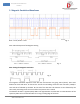
ID-2/12/20 LA Series Datasheet X1 11.04.2013 5. Magnetic Emulation Waveforms Blue = Clock, Brown = Data Fig. 3 Start and End Sequences for Magnetic Timing Fig. 4 Data Timings for Magnetic Emulation Fig. 5 The magnetic Emulation Sequence starts with the Card Present Line going active (down). There next follows 10 clocks with Zero ‘0’ data. At the end of the 10 leading clocks the start character (11010) is sent and this is followed by the data.
ID-2/12/20 LA Series Datasheet X1 11.04.2013 6.
ID-2/12/20 LA Series Datasheet X1 11.04.2013 Pin11 is the DC supply pin. The supply voltage must be free from noise and preferably from a linear regulator with less than 3mV PKPK noise. Many modern regulators have noise below 100uV RMS and these are ideal. See the section on choice of power supply. 7. Absolute Maximum Ratings Maximum voltage applied to Pin 2 (Vcc) 5.5volt Maximum voltage applied to Pin 2 (Reset) Vcc + 0.7v, -0.
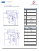
ID-2/12/20 LA Series Datasheet X1 11.04.2013 8. Circuit Diagram 8.1 Circuit Diagram for ID-12LA, ID-20LA Parts List Part # Value R1 100R R2 4K7 R3 2K2 C1 10uF 25v electrolytic C2 1000uF 10v electrolytic C3 100nF Q1 BC457 or similar LED1 Read LED LED2 Tag In Range LED B1 2.7khz – 3kHz 5v PKPK AC Parts List 8.2 Circuit Diagram for ID-2LA www.id-innovations.com Part # Value R1 100R R2 4K7 R3 2K2 C1 10uF 25v electrolytic C2 1000uF 10v electrolytic C3 100nF L1 1.
ID-2/12/20 LA Series Datasheet X1 11.04.2013 9. Dimensions (mm) ID-2LA Nom. Min. Max. A 12.0 11.6 12.4 B 8.0 7.6 8.4 C 15.0 14.6 15.4 D 20.5 20.0 21.5 E 18.5 18.0 19.2 F 14.0 13.0 14.8 G 22.0 21.6 22.4 P 2.0 1.8 2.2 H 5.92 5.85 6.6 J 9.85 9.0 10.5 W 0.66 0.62 0.67 ID-12LA Nom. Min. Max. A 12.0 11.6 12.4 B 8.0 7.6 8.4 C 15.0 14.6 15.4 D 25.3 24.9 25.9 E 20.3 19.8 20.9 F 16.3 15.8 16.9 G 26.4 26.1 27.1 P 2.0 1.8 2.2 H 6.
ID-2/12/20 LA Series Datasheet X1 11.04.2013 ID-20LA Nom. Min. Max. A 12.0 11.6 12.4 B 8.0 7.6 8.4 C 15.0 14.6 15.4 D 40.3 40.0 41.0 E 27.8 27.5 28.5 F 22.2 21.9 23.1 G 38.5 38.2 39.2 P 2.0 1.8 2.2 H 6.8 6.7 7.0 J 9.85 9.4 10.6 W 0.66 0.62 0.67 www.id-innovations.
ID-2/12/20 LA Series Datasheet X1 11.04.2013 10. Connection direct to a computer Direct connection to a computer RS232 can be made by connecting Pin8 to a 1k series resistor and connecting the other end of the resistor to the computer RS232 input. The mode is called pseudo RS232. On a standard D9 socket, connect module Pin8 via the series 1k to pin2 of the D-type. Connect the ground to Pin5 on the D-type. Leave the TX pin3 open. See “Useful Information” below for free terminal download information.
ID-2/12/20 LA Series Datasheet X1 11.04.2013 12. Choice of Power Supply The choice of power supply is very important. The ideal power supply will be a linear type such as an LM7805 or a 3.3 volt equivalent. Batteries may also be used without a regulator, a suitable arrangement can consist of a 3volt lithium cell or 3x 1.5v cells to give 4.5 volts. Note that ID-Innovations will be introducing a low-range series of micro-power reader modules (current <1mA) with the same pin out.
ID-2/12/20 LA Series Datasheet X1 11.04.2013 13. Designing Coils for ID-2LA The recommended Inductance is 1.337mH to be used with the internal tuning capacitor of 1n2. In general the bigger the antenna the better, provided the reader is generating enough field strength to excite the tag. The ID-2LA is relatively low power so a maximum coil size of 15x15cm is recommended if it is intended to read ISO cards.
ID-2/12/20 LA Series Datasheet X1 11.04.2013 14. Fine Tuning the ID-2LA We recommend using an oscilloscope for fine-tuning. Connect the oscilloscope to observe the 125kHz AC voltage across the coil. Get a sizeable piece of ferrite and bring it up to the antenna loop. If the voltage increases then more inductance is required. If the voltage decreases as the ferrite is brought up to the antenna then the inductance is too great.
ID-2/12/20 LA Series Datasheet X1 11.04.2013 15. ID-2LA Compatibility Issues with the ID-2 With the exception of pin6, which should be left unconnected in the ID-2, and which now serves as a ‘Tag in range Pin’, the ID2-LA is 100% pin compatible and supply voltage compatible with the ID-2 and its read and output data functionality is also 100% compatible, the only difference is the RF drive power and tuning. The original ID-2 employed an internal 1n5 (0.0015uF) capacitor and an external 1.
ID-2/12/20 LA Series Datasheet X1 11.04.2013 5) Use a linear regulator for the supply if possible. If a switching power must be used then see the section on choice of power supply. 6) If a switching supply is present on the same mother board, and uses an inductor, consider rotating the inductor to obtain the least coupling with the module antenna. 7) Preferably power the beeper from another supply.
ID-2/12/20 LA Series Datasheet X1 11.04.2013 Disclaimer The information in this document is provided solely for the use of ID Innovations’ products. There are no express or implied copyright licenses or intellectual property rights granted to design or fabricate any of ID Innovations’ products based on the information provided in this document. ID Innovations reserves the right to make changes to specifications and product descriptions at any time without notice.