
Data Sheet

522
Atmel | SMART SAM D21 [DATASHEET]
Atmel-42181G–SAM-D21_Datasheet–09/2015
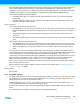
High-speed Mode
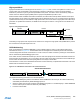
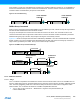
High-speed transfers are a multi-step process as shown in Figure 27-8. First, a master code (0000 1nnn where nnn is a
unique master code) is transmitted in Full-speed mode, followed by a NACK since no slave should acknowledge.
Arbitration is performed only during the Full-speed Master Code phase. The master code is transmitted by writing the
master code to the address register (ADDR) with the high-speed bit (ADDR.HS) written to zero.
After the Master Code and NACK have been transmitted, the master write interrupt will be asserted. At this point,
the slave address can be written to the ADDR register with the ADDR.HS bit set to one. The master will then generate a
repeated start followed by the slave address in High-speed mode. The bus will remain in High-speed mode until a stop is
generated. If a repeated start is desired, the ADDR.HS bit must again be written to 1 along with the new address to be
transmitted.
Figure 27-8. High Speed Transfer
Transmitting in High-speed mode requires the I2C master to be configured in High-speed mode (SPEED=0b10) and the
SCL clock stretch mode (SCLSM) bit set to one.
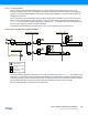
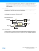
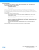
10-Bit Addressing
When 10-bit addressing is enabled (TENBITEN=1) and the ADDR register is written, the two address bytes will be
transmitted as shown in Figure 27-9. The addressed slave acknowledges the two address bytes and the transaction
continues. Regardless of whether the transaction is a read or write, the master must start by sending the 10-bit address
with the read/write bit (ADDR.ADDR[0]) equal to zero.
If the master receives a NACK after the first byte, then the write interrupt flag will be raised and the NACK bit will be set.
If the first byte is acknowledged by one or more slaves, then the master will proceed to transmit the second address byte
and the master will first see the write interrupt flag after the second byte is transmitted.
If the transaction is a read, the 10-bit address transmission must be followed by a repeated start and the first 7 bits of the
address with the read/write bit equal to 1.
Figure 27-9. 10-Bit Address Transmission for a Read Transaction
This implies the following procedure for a 10-bit read operation:
z Write ADDR.ADDR[10:1] with the 10-bit address. ADDR.TENBITEN must be set (can be written simultaneously
with ADDR) and read/write bit (ADDR.ADDR[0]) equal to 0.
z When the master write interrupt is asserted, write ADDR[7:0] register to “11110 address[9:8] 1”. ADDR.TENBITEN
must be cleared (can be written simultaneously with ADDR).
z Proceed to transmit data.
S
A
A/A
Sr
PA DATA
N Data Packets
Master Code
R/W
ADDRESS
Sr
ADDRESS
Hs-mode continues
F/S-mode
Hs-mode
F/S-mode
S AW
addr[7:0]
A
11110 addr[9:8]
Sr AR
1
S
W
MASTER WRITE INTERRUPT
11110 addr[9:8]