
Datasheet


addition, the master can generate read time slots after
issuing Convert T [44h] or Recall E
2
[B8h]commandsto
find out the status of the operation, as explained in the
Powering the MAX31820 section.
All read time slots must be a minimum of 60µs in duration
with a minimum of a 1µs recovery time between slots. A
read time slot is initiated by the master device pulling the
1-Wire bus low for a minimum of 1µs and then releasing
the bus (
Figure 10). After the master initiates the read
time slot, the device begins transmitting a 1 or 0 on the
bus. The device transmits a 1 by leaving the bus high and
transmits a 0 by pulling the bus low. When transmitting
a 0, the device releases the bus by the end of the time
slot, and the bus is pulled back to its high idle state by
the pullup resister. Output data from the device is valid
for 15µs after the falling edge that initiated the read time
slot. Therefore, the master must release the bus and then
sample the bus state within 15µs from the start of the slot.
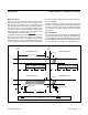
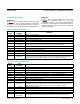
Figure 11 illustrates that the sum of t
INIT
, t
RC
, and
t
SAMPLE
must be less than 15µs for a read time slot.
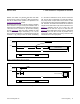
Figure12 shows that system timing margin is maximized
by keeping t
INIT
and t
RC
as short as possible and by
locating the master sample time during read time slots
towards the end of the 15µs period.
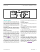
Figure 11. Detailed Master Read-One Timing
Figure 12. Recommended Master Read-One Timing
V
IH
OF MASTER
MASTER SAMPLES
V
PU
1-Wire BUS
GND
15µs
t
INIT
> 1µs t
RC
BUS MASTER PULLING LOW RESISTOR PULLUP
V
PU
V
IH
OF MASTER
t
INIT
=
SMALL
t
RC
=
SMALL
MASTER SAMPLES
15µs
1-Wire BUS
GND
BUS MASTER PULLING LOW RESISTOR PULLUP
MAX31820 1-Wire Ambient Temperature Sensor
www.maximintegrated.com
Maxim Integrated
│
18