
Data Sheet

MMA8452Q
Sensors
Freescale Semiconductor, Inc. 21
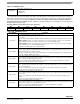
0x0C: INT_SOURCE System Interrupt Status Register
In the interrupt source register the status of the various embedded features can be determined. The bits that are set (logic ‘1’)
indicate which function has asserted an interrupt and conversely the bits that are cleared (logic ‘0’) indicate which function has
not asserted or has deasserted an interrupt. The bits are set by a low to high transition and are cleared by reading the
appropriate interrupt source register. The SRC_DRDY bit is cleared by reading the X, Y and Z data. It is not cleared by simply
reading the Status Register (0x00).
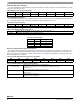
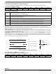
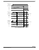
Table 13. SYSMOD Description
SYSMOD[1:0]
System Mode. Default value: 00.
00: STANDBY mode
01: WAKE mode
10: SLEEP mode
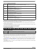
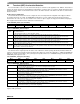
0x0C: INT_SOURCE: System Interrupt Status Register (Read Only)
Bit
7
Bit
6
Bit
5
Bit
4
Bit
3
Bit
2
Bit
1
Bit
0
SRC_ASLP 0 SRC_TRANS SRC_LNDPRT SRC_PULSE SRC_FF_MT 0 SRC_DRDY
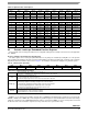
Table 14.
INT_SOURCE Description
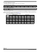
INT_SOURCE Description
SRC_ASLP
Auto-SLEEP/WAKE interrupt status bit. Default value: 0.
Logic ‘1’ indicates that an interrupt event that can cause a WAKE to SLEEP or SLEEP to WAKE system mode transition
has occurred.
Logic ‘0’ indicates that no WAKE to SLEEP or SLEEP to WAKE system mode transition interrupt event has occurred.
WAKE to SLEEP transition occurs when no interrupt occurs for a time period that exceeds the user specified limit
(ASLP_COUNT). This causes the system to transition to a user specified low ODR setting.
SLEEP to WAKE transition occurs when the user specified interrupt event has woken the system; thus causing the
system to transition to a user specified high ODR setting.
Reading the SYSMOD register clears the SRC_ASLP bit.
SRC_TRANS
Transient interrupt status bit. Default value: 0.
Logic ‘1’ indicates that an acceleration transient value greater than user specified
threshold
has
occurred. Logic ‘0’
indicates that no transient event has occurred.
This bit is asserted whenever “EA” bit in the TRANS_SRC is asserted and
the
interrupt
has been enabled. This bit is
cleared by reading the TRANS_SRC register.
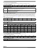
SRC_LNDPRT
Landscape/Portrait Orientation interrupt status bit. Default value: 0.
Logic ‘1’ indicates that an interrupt was generated due to a change in the device orientation status. Logic ‘0’ indicates
that no change in orientation status was detected.
This bit is asserted whenever “NEWLP” bit in the PL_STATUS is asserted and the
interrupt
has
been enabled.
This bit is cleared by reading the PL_STATUS register.
SRC_PULSE
Pulse interrupt status bit. Default value: 0.
Logic ‘1’ indicates that an interrupt was generated due to single and/or double pulse event. Logic ‘0’ indicates that no
pulse event was detected.
This bit is asserted whenever “EA” bit in the PULSE_SRC is asserted and the interrupt has been enabled.
This bit is cleared by reading the PULSE_SRC register.
SRC_FF_MT
Freefall/Motion interrupt status bit. Default value: 0.
Logic ‘1’ indicates that the Freefall/Motion function interrupt is active. Logic ‘0’ indicates that no Freefall or Motion event
was detected.
This bit is asserted whenever “EA” bit in the FF_MT_SRC register is asserted and the FF_MT interrupt has been
enabled.
This bit is cleared by reading the FF_MT_SRC register.
SRC_DRDY
Data Ready Interrupt bit status. Default value: 0.
Logic ‘1’ indicates that the X, Y, Z data ready interrupt is active indicating the presence of new data and/or data overrun.
Otherwise if it is a logic ‘0’ the X, Y, Z interrupt is not active.
This bit is asserted when the ZYXOW and/or ZYXDR is set and the interrupt has been enabled.
This bit is cleared by reading the X, Y, and Z data.