
Data Sheet

October 2017 BNO080 Datasheet 1000-3927
www.hillcrestlabs.com © 2017 Hillcrest Laboratories, Inc. All rights reserved. 14 / 57
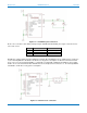
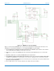
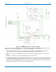
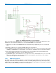
7. Pullup resistors (R1 and R2) are needed on the I
2
C communication lines – Pin 19 (HOST_SCL) and Pin 20
(HOST_SDA). These values may vary depending on the board design and bus capacitance, but typical
values are between 2KΩ and 4KΩ.
8. The BNO080 supports environmental sensors (e.g. pressure sensors, ambient light sensors) on a secondary
I
2
C interface. This interface should be pulled up via resistors regardless of the presence of the external
sensor as the SW polls for sensors at reset.
1.3.2.1 I
2
C Operation
The I
2
C specification is documented in [4]. The BNO080 provides a slave interface to the application processor
and supports 100kbps Standard mode (Sm) and 400kbps Fast mode (Fm).
I
2
C is a two-wire serial interface that consists of a serial clock line (SCL) and a serial data line (SDA). I
2
C allows
for multi-master, multi-slave communication and uses an open-drain architecture to enable this capability. All
devices that drive the SDA line or SCL line can only drive the line low (‘0’); the bus is released and pulled high by
the pull-up resistor for ‘1’s. The master device places the slave address on the data bus and the slave device with
the corresponding address acknowledges the master.
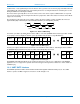
The BNO080 I
2
C interface answers to a 7-bit address of either 0x4A or 0x4B:
6
5
4
3
2
1
0
1
0
0
1
0
1
SA0
Figure 1-12: BNO080 I
2
C address
The lower address bit of the device address is provided by the SA0 pin. This pin is sampled at reset and should
be tied to either a logic high or logic low.
1.3.2.2 I
2
C Protocol
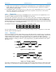
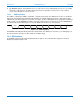
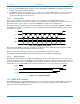
In general the data line should be stable while the clock is high, data transitions should therefore occur when the
clock is low. Communication on an I
2
C bus is initiated with the master device presenting a START command and
terminated with a STOP command. The bus is busy between the two commands. A START command (or
condition) is defined as a transition on the SDA signal from high to low while the SCL signal is high (Figure 1-13).
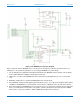
A STOP command (or condition) is defined as a low to high transition on the SDA signal while the SCL signal is
high (Figure 1-14).
Figure 1-13: I
2
C START condition
Figure 1-14: I
2
C STOP condition
I
2
C is a byte oriented protocol. Hence each element passed between the master and slave is 8-bits long. The bits
within the byte are transmitted most-significant bit (MSB) first. For multi-byte words the data is presented in little-
SDA
SCL
START condition
SDA
SCL
STOP condition