
Data Sheet

October 2017 BNO080 Datasheet 1000-3927
www.hillcrestlabs.com © 2017 Hillcrest Laboratories, Inc. All rights reserved. 28 / 57
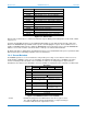
Byte
Description
6
Gyroscope calibrated Axis Y LSB
7
Gyroscope calibrated Axis Y MSB
8
Gyroscope calibrated Axis Z LSB
9
Gyroscope calibrated Axis Z MSB
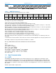
Figure 1-34: Calibrated gyroscope input report
The sequence number is a monotonically increasing value that is used to check for dropped samples.
The status byte is broken into two fields:
Bits 1:0 – indicate the status of a sensor.
0 – Unreliable
1 – Accuracy low
2 – Accuracy medium
3 – Accuracy high
Bits 7:2 - Delay upper bits: 6 most-significant bits of report delay
The delay byte is the lower 8 bits of the report delay. Delay has a resolution of 100µs.
Bytes 4-9 of the report provide the gyroscope data.
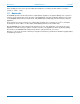
1.4.5.3 Timestamping
The sensor report delay field allows an accurate timestamp to be formed in the host application. Delay measures
the time delta from the sensor interrupt to the timebase reference. By generating a timestamp on the host
interrupt signal the host application can then determine an accurate sensor timestamp by subtracting delay.
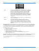
Note that the BNO080 also provides a timebase reference report with sensor reports:
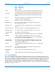
Byte
Description
0
Report ID=0xFB
1
Base Delta LSB: relative to transport-defined reference
point. Signed. Units are 100 microsecond ticks.
2
Base Delta
3
Base Delta
4
Base Delta MSB
Figure 1-35: Timebase Reference Report
The timebase reference functions in the same way as the delay field in the sensor report. The base delta should
be subtracted from the timestamp registered on the host for the host interrupt signal. When the timebase
reference report is provided the individual sensor report will likely have a delay of zero. However, in cases where
sensor reports are concatenated (due to delays in processing), the delay field may be populated, in which case
both that delay and the timebase reference should be taken into account when calculating the actual timestamp of
the sensor sample.
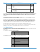
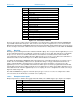
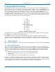
As an example, if the host receives the following report:
Figure 1-36: Timestamping example
The host will create a timestamp based on the assertion of HINT (call it T). The timebase reference provides a
baseline reference of 120 * 100µs or 12ms. All sensor reports are thus timestamped as T-12ms + their own delay.
Timebase
Reference
Delta = 120
Sensor report
Delay = 0
Sensor report
Delay = 17