
Data Sheet

October 2017 BNO080 Datasheet 1000-3927
www.hillcrestlabs.com © 2017 Hillcrest Laboratories, Inc. All rights reserved. 49 / 57
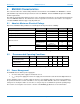
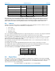
Composite Sensor
Calibration
Measurement
Performance Metric
Value
Geomagnetic Rotation Vector
Nominal
Dynamic
Rotation Error
4.5°
Static
Rotation Error
3.0°
Gravity
Nominal
Static
Angle Error
1.5°
Linear Acceleration
Nominal
Dynamic
Accuracy
0.35 m/s
2
Accelerometer
Nominal
Dynamic
Accuracy
0.3 m/s
2
Gyroscope
Nominal
Dynamic
Accuracy
3.1°/s
Magnetometer
Either
Dynamic
Accuracy
1.4uT
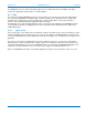
Figure 6-12: BNO080 Performance
The results above were generated by simulation. 210 physical devices were characterized and each of these
models was subjected to simulated motion and the variation from truth catalogued. The rotation vector and
geomagnetic rotation vector are highly dependent on the environmental conditions (specifically the magnetic
field). In practice the rotation vector is typically accurate to 5˚ and the geomagnetic rotation vector to 10˚.
6.8 Latency
Latency is a measure of the response of the BNO080 to motion and is typically reserved for continuous sensors.
The time to generate an output can be divided into several parameters:
• Sensor delay
• Processing delay
• Algorithmic delay
• Communication delay
The sensors within the BNO080 will generate an output reflecting motion or a measure of the magnetic field within
the sample period just measured. The sensor interrupt is assumed to be the end of the sample.
The processing time of the BNO080 is dependent on the output of interest. The output for fused sensors (rotation
vector, gravity etc.) follows a gyroscope sample and requires additional processing to fuse the gyroscope data
with the accelerometer and magnetometer data.
Processing time is measured from data becoming available from the sensor to data being made available to the
host (HOST_INTN asserted).
The algorithms present in SH-2 apply BW limiting filtering which in turn adds a small delay to the signal.
The communication delay is dependent upon the transfer speed of the communication medium chosen and the
host’s ability to respond to interrupts and support the maximum clock rate of the BNO080.
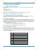
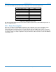
The measured latency for the BNO080 is provided in Figure 6-13.
Sensor
Typical latency
100Hz
200Hz
Gyro rotation vector
6.6ms
3.7ms
Rotation vector
6.6ms
3.7ms
Game rotation vector
6.6ms
3.7ms
Figure 6-13: Typical latency measurements
6.9 Report Rates
The number of reports per second that the BNO080 can reliably deliver is dependent on the interface bandwidth
and the processing time within the BNO080 for the generation of the data. The sensors also have discrete sample
rates which must be taken into account when configuring the device. The BNO080 will attempt to satisfy the
requested rate based on the following formula:
0.9 * RequestedRate <= ConfiguredRate <= 2.1 * RequestedRate