Preliminary Datasheet SGP40 Indoor Air Quality Sensor for VOC Measurements MOx based gas sensor for indoor air quality applications Outstanding long-term stability and lifetime I2C interface with digital output signal Very small 6-pin DFN package: 2.44 x 2.44 x 0.85 mm3 Low power consumption: 2.6 mA at 3.3 V Tape and reel packaged, reflow solderable Product Summary The SGP40 is a digital gas sensor designed for easy integration into air purifiers or demand-controlled ventilation systems.
Table of Contents 1 Sensor Performance ..................................................................................................................................................................3 2 Specifications.............................................................................................................................................................................5 3 Sensor Output Signal Description ...................................................................................
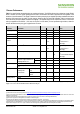
1 Sensor Performance Table 1 lists specifications characterizing the gas sensing performance. The SGP40 chip provides a digital raw signal (SRAW) which is sensitive to all VOC gases typically present in indoor environments and which is proportional to the logarithm of the resistance of the MOx material. This signal is intended for further processing by an algorithm providing quantitative information about the VOC based indoor air quality.
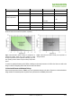
Figure 2 displays the typical response of the raw signal of SGP40 to various VOCs as a function of their concentrations in otherwise clean air. Figure 2 Typical sensor response to various VOCs normalized to 500 ppb of ethanol. Data were recorded at 25 °C and 50 % RH and a power supply of VDD of 3.3 V. www.sensirion.com Version 1.
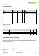
2 Specifications 2.1 Electrical Specifications Table 2 lists electrical specifications of the SGP40. Default conditions of 25 °C and 3.3 V supply voltage apply to values in the table below, unless otherwise stated. The SGP40 supports both I2C “standard-mode” and “fast-mode”.9 Parameter Values Symbol Min. Supply voltage, hotplate supply voltage10 VDD, VDDH Idle current IDD Supply current under operation11 Communication – Typ. Max. Unit Comments 1.7 3.3 3.
Condition Parameter Min. Max. Unit Operating conditions Relative humidity 0 90 % RH Temperature −10 50 °C Humidity 1.5 (−13) 30 (+31) – 90 (the smaller) g m−3 (°C dew point) or % RH Temperature −10 50 °C Relative humidity 0 80 % RH Temperature 5 30 °C Operating conditions of humidity compensation Storage conditions Table 4 Recommended humidity and temperature conditions for storing and operating the SGP40.
Parameter Rating Supply voltage VDD −0.3 to +3.6 V Supply voltage VDDH −0.3 to +3.6 V Short-term storage temperature range12 −40 to +70 °C Operating temperature range −20 to +55 °C Short-term storage humidity range12 0 to 80 % (non-condensing) Operating humidity range 0 to 90 % (non-condensing) ESD HBM 2 kV ESD CDM 500 V Latch up, JESD78 Class II, 125 °C 100 mA Table 5 Absolute minimum and maximum ratings. 2.5 Interface Specifications The SGP40 comes in a 6-pin DFN package, see Table 6.
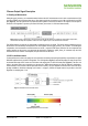
Figure 5 Typical application circuit. 2.6 Environmental Stability The SGP40 has been qualified based on the JEDEC JESD47 qualification test method. The Moisture Sensitivity Level classification of the SGP40 is MSL1, according to IPC/JEDEC J-STD-020. At the same time, it is recommended to further process the sensors within 1 year after date of delivery. The SGP40 should not be exposed to bright illumination by either sunlight or artificial light sources during operation. 2.
3 Sensor Output Signal Description 3.1 Raw Signal Measurement Calling the sgp40_measure_raw command launches/continues the VOC measurement mode. It starts one measurement of the raw signal (SRAW) which is returned after 30 ms. Raw signal value in ticks is provided as one 16-bit word followed by one CRC byte (Figure 6). The raw signal in ticks is proportional to the logarithm of the sensor resistance. This signal is used as input for Sensirion’s VOC Algorithm to provide a processed VOC Index (see section 3.
3.3 Built-in Self-Test With the sgp40_measure_test command, users can perform an on-chip self-test for, e.g., in-line or end-of-line production testing. If this command is called when the sensor is in idle mode, the sensor returns to idle mode after the test (Figure 9). In case this command is called during VOC measurement mode (i.e., after calling the sgp40_measure_raw command), the hotplate remains switched on thereafter.
4 Digital Interface Description 4.1 General Considerations For driver integration incl. utilization of Sensirion’s VOC Algorithm, please refer to the application note SGP40 Driver Integration (for Dedicated I2C Hardware). All SGP40 commands consist of two bytes (16 bits). The commands must not be followed by a CRC. Additionally, data sent to and returned from the sensor is transferred in packets of two bytes (16 bits) followed by a 1-byte (8 bit) CRC. 4.
4.6 Checksum Calculation The 8-bit CRC checksum transmitted after each data word is generated by the CRC algorithm according to the properties as stated in Table 7. The CRC covers the contents of the two previously transmitted data bytes.
Measure Raw Signal Command Subcommand Command hex. code Description sgp40_measure_raw Without humidity compensation 0x26 0F 80 00 A2 66 66 93 This command starts/continues the VOC measurement mode, leaves humidity compensation disabled by sending the default values (see Table 10), and returns the measured raw signal SRAW as 2 bytes (+ 1 CRC byte).
Byte number Description Value 0, 1 two bytes 0xD4 00: all tests passed successfully 0x4B 00: one or more tests have failed 2 CRC byte for bytes 0, 1 – Table 13 Returned values by the I2C built-in self-test command. Return to Idle Mode Command Command hex. code Description sgp40_heater_off 0x36 15 This command turns the hotplate off and stops the measurement. Subsequently, the sensor enters the idle mode. Table 14 Description of the I2C heater off command. Soft Reset Command Command hex.
5 Mechanical Specifications SGP40 sensors are provided in a DFN (dual flat no leads) package with an outline of 2.44 × 2.44× 0.85 mm3 and a terminal pitch of 0.8 mm. The sensor opening with a typical diameter of 0.8 mm is offset to the bottom right corner on the top side of the package. The sensor chip is assembled on a Ni/Pd/Au plated copper lead frame. Sensor chip and lead frame are over-molded by a black, epoxy-based mold compound.
5.3 Land Pattern Recommended land pattern of the SGP40 is shown in Figure 13. Pads on PCB are recommended to be non-solder mask defined (NSMD). Recommended solder paste stencil thickness is 125–150 m. Figure 13 Recommended land pattern. 5.4 Soldering Instructions Standard reflow soldering ovens and “no clean” type 3 solder paste (as specified in IPC J-STD-005A) should be used for soldering the SGP40. The sensors are designed to withstand a soldering profile according to IPC/JEDEC J-STD-020.
6 Ordering Information Use the part names and product numbers shown in the following table when ordering the SGP40 gas sensor and accessories. For the latest product information and local distributors, visit www.sensirion.com. Part Name Description Ordering size Product Number SGP40-D-R4 SGP40 sensor components as tape on reel 2’500 pcs 3.000.384 Table 16 SGP40 ordering options. 6.1 Packaging Information Figure 15 Technical drawing of the packaging tape with sensor orientation in tape.
Important Notices Warning, Personal Injury Do not use this product as safety or emergency stop devices or in any other application where failure of the product could result in personal injury. Do not use this product for applications other than its intended and authorized use. Before installing, handling, using or servicing this product, please consult the data sheet and application notes. Failure to comply with these instructions could result in death or serious injury.
Revision History Date Version Page(s) Changes July, 2020 1.0 All Initial release Headquarters and Subsidiaries Sensirion AG Laubisruetistr. 50 CH-8712 Staefa ZH Switzerland Sensirion Inc., USA phone: +1 312 690 5858 info-us@sensirion.com www.sensirion.com Sensirion Korea Co. Ltd. phone: +82 31 337 7700~3 info-kr@sensirion.com www.sensirion.com/kr phone: +41 44 306 40 00 fax: +41 44 306 40 30 info@sensirion.com www.sensirion.com Sensirion Japan Co. Ltd. phone: +81 3 3444 4940 info-jp@sensirion.