
Datasheet
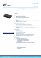

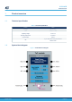
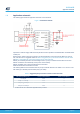

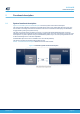


Table Of Contents
- Cover image
- Device summary
- Features
- Applications
- Description
- 1 Product overview
- 2 Functional description
- 3 Control interface
- 4 Electrical characteristics
- 5 Ranging performances
- 6 Outline drawings
- 7 Field of view (FoV) and field of illumination (FoI)
- 8 Laser safety considerations
- 9 Packaging and labeling
- 10 Package information
- 11 Ordering information
- Revision history
- Contents

2.2 State machine description
The following figure shows the device state machine.
Figure 5. Device state machine
2.3 Customer manufacturing calibration flow
Up to two calibrations are needed to ensure the best sensor performances. Offset needed in all applications. If a
cover glass is used, cross-talk calibration is needed also.
The detailed procedure is provided in the VL53L4CD Ultra Lite Driver user manual (UM2931).
2.4 Device programming and control
The device physical control interface is I2C, described in Section 3 Control interface.
A software layer (driver) is provided to control the device. This avoids complex I2C register operations with
turnkey functions to start, stop and read the ranging values.
The driver structure and functions are described in the VL53L4CD Ultra Lite Driver user manual.
2.5 Digital processing and reading the results
Digital processing is the final operation of the ranging sequence that computes, validates or rejects a ranging
measurement.All the processing is performed by the VL53L4CD internal firmware. The software driver allows
reading the results when they are valid.
If the distance cannot be measured (no target or weak signal), a corresponding status error code is generated
and can be read by the host.
A full description of the status errors is provided in the VL53L4CD Ultra Lite Driver user manual (UM2931).
VL53L4CD
State machine description
DS13812 - Rev 3
page 8/36