
Schematic
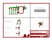

SDOM/AG
AG Addr.
0
1
M Addr.
Set the SDO_AG and SDO_M to set the
accel/gryo and mag I2C addresses:
JP1 pulls the SDA and SCL data lines
high through R1 and R2. To disable pull-up
resistors, cut traces on both sides.
JP2 sets the I2C address for the
accelerometer and gyroscope.
JP3 sets the I2C address for the
magnetometer.
0x6A
0x6B*
0x1C
0x1E*
* Default address
VDD: 1.9-3.6V
LSM9DS1
VDD
10uF 0.1uF
0.1uF
0.1uF
10nF
4.7K
4.7K
VDD
GND GND GND GND GND
VDD
GND
VDD
VDD
GND
VDD
GND
GND
19*2
C1
24
CAP
21
DEN_A/G
13
INT_M
10
DRDY_M
9
INT1_A/G
11
INT2_A/G
12
VDD
22*2
VDDIO
1*2
CS_M
8
CS_A/G
7
SCL/SPC
2
SDO_M
6
SDO_A/G
5
SDA/SDI/SDO
4
U1
RES
14*5
C1 C2
C3
C5
C4
R1
R2
JP1
J2
1
2
3
4
JP2
JP3
SCL
SCL
SCL
SDA
SDA
SDA
SDO_A/G
SDO_A/G
SDO_M
SDO_M
Alex Wende
v21
LSM9DS1
I2C Address
Table
HeaderJumpers
Released under the Creative Commons
Attribution Share-Alike 4.0 License
https://creativecommons.org/licenses/by-sa/4.0/
Design by: