
Data Sheet
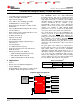
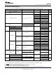

TCA9548A
Slaves A0, A1...AN
Slaves B0, B1...BN
Slaves H0, H1...HN
I2C or SMBus
Master
(processor)
SDA
SCL
SD0
SC0
Channel 0
Channel 1
Channel 7
RESET
SD1
SC1
SD7
SC7
VCC
A1
A2
GND
A0
Slaves C0, C1...CN
Channel 2
SD2
SC2
Product
Folder
Sample &
Buy
Technical
Documents
Tools &
Software
Support &
Community
An IMPORTANT NOTICE at the end of this data sheet addresses availability, warranty, changes, use in safety-critical applications,
intellectual property matters and other important disclaimers. PRODUCTION DATA.
TCA9548A
SCPS207F –MAY 2012–REVISED NOVEMBER 2016
TCA9548A Low-Voltage 8-Channel I
2
C Switch with Reset
1
1 Features
1
• 1-to-8 Bidirectional Translating Switches
• I
2
C Bus and SMBus Compatible
• Active-Low Reset Input
• Three Address Pins, Allowing up to Eight
TCA9548A Devices on the I
2
C Bus
• Channel Selection Through an I
2
C Bus, In Any
Combination
• Power Up With All Switch Channels Deselected
• Low R
ON
Switches
• Allows Voltage-Level Translation Between 1.8-V,
2.5-V, 3.3-V, and 5-V Buses
• No Glitch on Power Up
• Supports Hot Insertion
• Low Standby Current
• Operating Power-Supply Voltage Range of
1.65 V to 5.5 V
• 5-V Tolerant Inputs
• 0- to 400-kHz Clock Frequency
• Latch-Up Performance Exceeds 100 mA Per
JESD 78, Class II
• ESD Protection Exceeds JESD 22
– ±2000-V Human-Body Model (A114-A)
– 200-V Machine Model (A115-A)
– ±1000-V Charged-Device Model (C101)
2 Applications
• Servers
• Routers (Telecom Switching Equipment)
• Factory Automation
• Products With I
2
C Slave Address Conflicts (Such
as Multiple, Identical Temperature Sensors)
3 Description
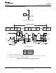
The TCA9548A device has eight bidirectional
translating switches that can be controlled through
the I
2
C bus. The SCL/SDA upstream pair fans out to
eight downstream pairs, or channels. Any individual
SCn/SDn channel or combination of channels can be
selected, determined by the contents of the
programmable control register. These downstream
channels can be used to resolve I
2
C slave address
conflicts. For example, if eight identical digital
temperature sensors are needed in the application,
one sensor can be connected at each channel: 0-7.
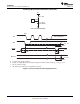
The system master can reset the TCA9548A in the
event of a time-out or other improper operation by
asserting a low in the RESET input. Similarly, the
power-on reset deselects all channels and initializes
the I
2
C/SMBus state machine. Asserting RESET
causes the same reset and initialization to occur
without powering down the part. This allows recovery
should one of the downstream I
2
C buses get stuck in
a low state.
The pass gates of the switches are constructed so
that the VCC pin can be used to limit the maximum
high voltage, which is passed by the TCA9548A.
Limiting the maximum high voltage allows the use of
different bus voltages on each pair, so that 1.8-V, 2.5-
V or 3.3-V parts can communicate with 5-V parts,
without any additional protection. External pullup
resistors pull the bus up to the desired voltage level
for each channel. All I/O pins are 5-V tolerant.
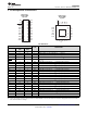
Device Information
(1)
PART NUMBER PACKAGE BODY SIZE (NOM)
TCA9548A
TSSOP (24) 7.80 mm × 4.40 mm
VQFN (24) 4.00 mm × 4.00 mm
(1) For all available packages, see the orderable addendum at
the end of the data sheet.
Simplified Application Diagram