
Data Sheet


MLX90393
Micropower Triaxis® Magnetometer Datasheet
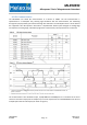
The argument in all mode-starting commands (SB/SW/SM) is a nibble specifying the conversions to be
performed by the sensor in the following order «zyxt». For example, if only Y axis and temperature are to be
measured in Single Measurement mode the correct command to be transmitted is 0x35h. The sequence of
measurement execution on-chip is inverted to «TXYZ», so T will be measured before X, followed by Y and
finally Z. By issuing an all-zero «zyxt» nibble, the BURST_SEL value from RAM will be used instead of the
empty argument of the command.
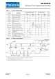
8.2 Status Byte
The status byte is the first byte transmitted by the MLX90393 in response to a command issued by the
master. It is composed of a fixed combination of informative bits:
bit 7
bit 6
bit 5
bit 4
bit 3
bit 2
bit 1
bit 0
BURST_MODE
WOC_MODE
SM_MODE
ERROR
SED
RS
D1
D0
• MODE bits
these bits define in which mode the MLX90393 is currently set. Whenever a mode transition command is
rejected, the first status byte after this command will have the expected mode bit cleared, which serves as
an indication that the command has been rejected, next to the ERROR bit. The SM_MODE flag can be the
result of an SM command or from raising the TRG pin when TRG mode is enabled in the volatile memory of
the MLX90393.
• ERROR bit
this bit is set in case a command has been rejected or in case an uncorrectable error is detected in the
memory, a so called ECC_ERROR. A single error in the memory can be corrected (see SED bit), two errors
can be detected and will generate the ECC_ERROR. In such a case all commands but the RT (Reset)
command will be rejected. The error bit is equally set when the master is reading back data while the DRDY
flag is low.
• SED bit
the single error detection bit simply flags that a bit error in the non-volatile memory has been corrected. It
is purely informative and has no impact on the operation of the MLX90393.
• RS bit
whenever the MLX90393 gets out of a reset situation – both hard and soft reset – the RS flag is set to
highlight this situation to the master in the first status byte that is read out. As soon as the first status byte
is read, the flag is cleared until the next reset occurs.
• D[1:0] bits
these bits only have a meaning after the RR and RM commands, when data is expected as a response from
the MLX90393. The number of response bytes correspond to 2*D[1:0] + 2, so the expected byte counts are
either 2, 4, 6 or 8. For commands where no response is expected, the content of D[1:0] should be ignored.
3901090393 Data Sheet
Rev002 Page 13 Feb-2015