
Data Sheet

October 2017 BNO080 Datasheet 1000-3927
www.hillcrestlabs.com © 2017 Hillcrest Laboratories, Inc. All rights reserved. 20 / 57
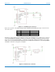
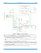
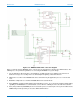
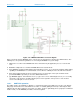
Figure 1-23: BNO080 UART-RVC connection diagram
Figure 1-23 shows how the BNO080 can be connected to an external microcontroller via a UART interface. The
following notes are provided as guidelines for connecting the BNO080 in a system design.
1. NRST is the reset line for the BNO080 and can be either driven by the application processor or the board
reset.
2. BOOTN is sampled at reset. If low the BNO080 will enter bootloader mode.
3. Pin 4 (BOOTN) should be pulled high through a 10K Ohms resistor. To use the device firmware update (DFU)
capability of the BNO080, it is recommended to connect Pin 4 to a GPIO pin on the external microcontroller.
4. Pin 5 (PS1) and Pin 6 (PS0) are the host interface protocol selection pins. These pins should be tied to
ground and VDDIO respectively to select the UART-RVC interface.
5. The BNO080 supports environmental sensors (e.g. pressure sensors, ambient light sensors) on a secondary
I
2
C interface. This interface should be pulled up via resistors regardless of the presence of the external
sensor as the SW polls for sensors at reset.
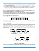
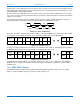
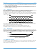
1.3.5.1 UART-RVC operation
The UART operates at 115200 b/s, 8 data bits, 1 stop bit and no parity. The UART protocol relies on an idle line
being ‘high’. A transmission is started with the assertion of a start bit (pulling the line low), followed by the data,
LSB first. After the data segment is sent (in this case 8-bits), the line is pulled high (the stop signal) for a minimum
number of bits (1 for the BNO080) to indicate end of that segment.