
Data Sheet

October 2017 BNO080 Datasheet 1000-3927
www.hillcrestlabs.com © 2017 Hillcrest Laboratories, Inc. All rights reserved. 40 / 57
4 BNO080 Orientation
The BNO080 can be mounted in an arbitrary manner that facilitates the manufacture of the device it is included
within. The outputs of the BNO080 must however be aligned to a frame of reference that is practical to the user.
This essentially requires mapping the orientation of the BNO080 to the orientation of the device within which it is
housed. Re-mapping of the BNO080’s sensor outputs to the supporting device’s frame of reference is achieved
by programming an FRS record. The system orientation FRS record (0x2D3E) applies a rotation to the sensor
outputs and all the derived outputs (e.g. rotation vectors). The system orientation record is a unit quaternion, with
each coordinate represented as a 32-bit fixed point number with a Q-point of 30 to represent a fractional number.
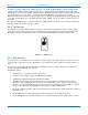
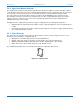
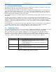
The default BNO080 axis orientation is shown in Figure 4-1. A positive value is reported for counter-clockwise
rotations.
Figure 4-1: BNO080 axis orientation
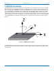
If the BNO080 was mounted such that its positive Y-axis was aligned opposite to the X-axis of the device it was
mounted in, but with its Z-axis aligned correctly, a clockwise rotation of 90˚ around the Z-axis would be required
(see Figure 4-2).