Simblee™ RFD77402 Simblee™ RFD77402 IoT 3D ToF Sensor Module Simblee™ IoT 3D ToF Sensor Module RFD77402 DATASHEET Features Fully Integrated microelectronic device with an embedded sensor and VCSEL(Vertical Cavity Surface Emitting Laser) • 850 nm VCSEL and electronic driver • Optical receiver sensor and optics • Microelectronic controller Time-of-Flight (ToF) is a highly accurate distance mapping and 3D imaging technology Eye safe invisible infrared (IR) illumination using a class 1 las
Simblee™ RFD77402 Contents Features ........................................................................................................................................................................................1 Applications ...................................................................................................................................................................................1 1 General Characteristics ......................................................................
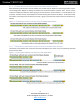
Simblee™ RFD77402 2.2.2 Power-up and power-down Sequence ...........................................................................................................................16 Figure 14: I2C SCL/SDA Power-up/down Sequence ..............................................................................................................16 2.3 Module Programming Interface ......................................................................................................................................
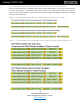
Simblee™ RFD77402 Figure 17: Scatter Chart Showing Measured Distances Versus Actual Distance...................................................................31 4.2 Maximum Ranging Distance and Ranging Accuracy .....................................................................................................32 Table 29: Range Accuracy Information in the Range of 50mm to 2000mm ...........................................................................32 5 Mechanical Dimensions ........................
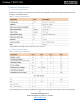
Simblee™ RFD77402 1 General Characteristics 1.1 Technical Specifications Performance and power consumption can be tuned to the application needs by changing configuration and/or through a customized firmware. Table 1: Technical Specifications (*) target with 90% reflectivity in dark environment and no cover glass 1.2 Electrical Specifications Table 2: Electrical Characteristics (*) Note that a pull-up to 1.8V implies that INT pin is configured as open drain (failure in doing so will cause high leakage).
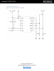
Simblee™ RFD77402 1.3 System Block Diagram and Device Pinout Figure 1: RFD77402 Block Diagram and Device Pinout (top view) Table 3: Device Pinout 6 RFD77402 DATASHEET v1.8 © 2017 RF Digital Corporation 7.24.2017 www.simblee.
Simblee™ RFD77402 1.4 Electrical Connectivity Figure 2: Electrical Connectivity Schematic 7 RFD77402 DATASHEET v1.8 © 2017 RF Digital Corporation 7.24.2017 www.simblee.
Simblee™ RFD77402 2 Module Interface 2.1 Electrical Interface The Simblee Time-of-Flight (TOF) Module interface is a standard 7-big address I2C slave (slave ID 0x4C) device capable up to 1Mbit/s. The ToF module I2C interface supports a direct 8-bit addressing scheme used to access the module user’s register set. This addressing scheme is functional also during standby mode since the module interface and the user’s register set remain powered for a faster response.
Simblee™ RFD77402 2.1.2 I2C Write Access with Auto Increment and Word Mode Features When performing a burst write to the I2C interface, the module response depends on the setting of bits 1:0 of the I2C Init Configuration Register controlling the address auto increment features and word mode. If none of these modes are enabled, the data burst write is going to be directed to the same I2C address.
Simblee™ RFD77402 2.1.4 I2C Write Indirect Addressing with Address Auto Increment and Word Mode As previously mentioned, the ToF module supports an I2C indirect address scheme. In this case, the 16-bit address is written to the register. Each subsequent byte will be written to the 16-bit address location pointed by the register in a manner that depends on bits 2:3 of the I2C Init of the Configuration Register (address auto increment and word mode control bits).
Simblee™ RFD77402 Figure 8: I2C Indirect Address Write with Address Auto Increment and Word Mode (2-Byte Access) 2.1.5 I2C Read Indirect Addressing with Address Auto Increment and Word Mode The indirect addressing I2C read follows the same rules as described above in terms of address auto increment and word mode. Figure 9: I2C Burst Read Indirect Addressing 11 RFD77402 DATASHEET v1.8 © 2017 RF Digital Corporation 7.24.2017 www.simblee.
Simblee™ RFD77402 Figure 10: I2C Indirect Address Read with Address Auto Increment and Word Mode (1-Byte Access 12 RFD77402 DATASHEET v1.8 © 2017 RF Digital Corporation 7.24.2017 www.simblee.
Simblee™ RFD77402 Figure 11: I2C Indirect Address Read with Address Auto Increment and Word Mode (2-Byte Access) 13 RFD77402 DATASHEET v1.8 © 2017 RF Digital Corporation 7.24.2017 www.simblee.
Simblee™ RFD77402 2.1.6 I2C Timing Information Figure 12: I2C Timing Characteristics Definitions Table 2: I2C Timing Characteristics Information 14 RFD77402 DATASHEET v1.8 © 2017 RF Digital Corporation 7.24.2017 www.simblee.
Simblee™ RFD77402 2.2 Host Interface Power Management The module enters standby mode once power is applied. To wake up the module to a fully on state (MCPU responding) the user must set to ‘1’ bit 9 (“MCPU_Init_State”) of the register PMU Configuration Register at address 0x14 and then issue a command that will then cause the MCPU to wake up. A command issued to the module with “MCPU_Init_State” not set to ‘1’ will cause the module to exit the Standby state and go in MCPU OFF state.
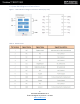
Simblee™ RFD77402 2.2.1 Standby / Leakage in Different Electrical Conditions Table 5: I2C SCL/SCA Power-up/down Sequence 2.2.2 Power-up and power-down Sequence Figure 14 below shows the RFD77402 power up and power down sequence. Please note that the module itself has no restrictions in terms of VDD and VI2C_pull-up sequencing, but in the case of VDD ON while VI2C_pull-up supply unit offers a path to GND. The value of such leakage current depends on the power supply impedance to GND.
Simblee™ RFD77402 Table 6: Host Interface Registers 17 RFD77402 DATASHEET v1.8 © 2017 RF Digital Corporation 7.24.2017 www.simblee.
Simblee™ RFD77402 2.3.1 Configuration Parameters Table 7: Configuration Parameters Used to Configure the Module 18 RFD77402 DATASHEET v1.8 © 2017 RF Digital Corporation 7.24.2017 www.simblee.
Simblee™ RFD77402 2.3.2 Module Interface Registers The following registers are used by the system host for module configuration and for operational communication. The user should not attempt to modify reserved fields as this could cause unpredictable behavior. Table 8: Interrupt Control Status Register 19 RFD77402 DATASHEET v1.8 © 2017 RF Digital Corporation 7.24.2017 www.simblee.
Simblee™ RFD77402 Table 9: Interrupt Enable Register Table 10: Command Register 20 RFD77402 DATASHEET v1.8 © 2017 RF Digital Corporation 7.24.2017 www.simblee.
Simblee™ RFD77402 Table 11: Device Status Register Table 12: Result Register 21 RFD77402 DATASHEET v1.8 © 2017 RF Digital Corporation 7.24.2017 www.simblee.
Simblee™ RFD77402 Table 13: Result Confidence Register Table 14: Command Configuration Register A Table 15: Command Configuration Register B 22 RFD77402 DATASHEET v1.8 © 2017 RF Digital Corporation 7.24.2017 www.simblee.
Simblee™ RFD77402 Table 16: Host to MCPU Mailbox Register Table 17: MCPU to Host Mailbox Register 23 RFD77402 DATASHEET v1.8 © 2017 RF Digital Corporation 7.24.2017 www.simblee.
Simblee™ RFD77402 Table 18: PMU Configuration Register Table 19: I2C Address Pointer Register 24 RFD77402 DATASHEET v1.8 © 2017 RF Digital Corporation 7.24.2017 www.simblee.
Simblee™ RFD77402 Table 20: I2C Data Port Register Table 21: I2C Init Configuration Register 25 RFD77402 DATASHEET v1.8 © 2017 RF Digital Corporation 7.24.2017 www.simblee.
Simblee™ RFD77402 Table 22: MCPU Power Management Control Register 2.3.3 Hardware Configuration Registers These registers are used for hardware or firmware configuration and typically set up once at power up. Table 23: HW/FW Configuration Register 0 Table 24: HW/FW Configuration Register 1 26 RFD77402 DATASHEET v1.8 © 2017 RF Digital Corporation 7.24.2017 www.simblee.
Simblee™ RFD77402 Table 25: HW/FW Configuration Register 2 Table 26: HW/FW Configuration Register 3 27 RFD77402 DATASHEET v1.8 © 2017 RF Digital Corporation 7.24.2017 www.simblee.
Simblee™ RFD77402 2.3.4 Other I2C Host Registers Table 27: Module Chip ID Register Table 28: Patch Memory Configuration Control Register 28 RFD77402 DATASHEET v1.8 © 2017 RF Digital Corporation 7.24.2017 www.simblee.
Simblee™ RFD77402 3 Programming Guide 3.1 Programming Flow Charts Figure 15: Power-up Initialization 29 RFD77402 DATASHEET v1.8 © 2017 RF Digital Corporation 7.24.2017 www.simblee.
Simblee™ RFD77402 3.1.1 Single Measure Figure 16: Single Measure Flow Chart 30 RFD77402 DATASHEET v1.8 © 2017 RF Digital Corporation 7.24.2017 www.simblee.
Simblee™ RFD77402 4 Performance 4.1 Measurement Conditions and Accuracy In all measurement tables in this document, it is considered that the full Field of View (FoV) is covered. Figure 17 below shows a scatter chart for the measured distance in mm versus the actual distance in mm. The target used here was a gray chart with 17% reflectivity. The red dotted lines indicate the specified ± 10% for maximum deviation allowed within the operational range of the device which is from 100mm to 2000mm.
Simblee™ RFD77402 4.2 Maximum Ranging Distance and Ranging Accuracy Table 29 below shows the ranging accuracy specifications of the device. The data for these measurements were obtained with the device operating at room temperature and there was no cover glass on the device when the measurements were performed.
Simblee™ RFD77402 5 Mechanical Dimensions Figure 18: Overall Dimensions Figure 19: Landing Pad and Solder Pad Recommendation 33 RFD77402 DATASHEET v1.8 © 2017 RF Digital Corporation 7.24.2017 www.simblee.
Simblee™ RFD77402 Figure 20: Field of View (FoV) and Field of Illumination (FoI) 6 Cover Glass Selection Guide To obtain the best performance, the following rules should be taken in account for the Cover Glass: • Material: PMMA, Acrylic • Spectral transmittance: T< 5% for λ< 770nm, T> 90% for λ > 820nm • Air gap: 100 µm • Thickness: < 1mm (the thinner, the better) • Dimensions bigger than 6x8mm • All the surfaces of the CG not relevant for the VCSEL emission and signal detection (e.g.
Simblee™ RFD77402 Table 30: Recommended Reflow Profile 35 RFD77402 DATASHEET v1.8 © 2017 RF Digital Corporation 7.24.2017 www.simblee.
Simblee™ RFD77402 8 Packaging (Tape and Reel Dimensions) Figure 22: Product Packaging Arrangement 36 RFD77402 DATASHEET v1.8 © 2017 RF Digital Corporation 7.24.2017 www.simblee.
Simblee™ RFD77402 9 Storage Conditions The RFD77402 module is an MSL 3 package. Table 31: Recommended Storage Conditions After this limit, dry bake to be done; 6 hours at 85ºC 10 RoHS and REACH Compliance The RFD77402 module is compliant with the European RoHS Directive 2002/95/EC (Restriction of the Use of Certain Hazardous Substances in Electrical and Electronic Equipment) and REACH (Registration, Authorization and Restriction of Chemicals, European Union Regulation (EC 1907/2006).
Simblee™ RFD77402 Disclaimer RF Digital, a subsidiary of Heptagon, a member of the ams group its affiliates, agents, and employees, and all persons acting on its or their behalf (collectively, “RF Digital”), disclaims any and all liability for any errors, inaccuracies or incompleteness contained in any datasheet or in any other disclosure relating to any product.