
User's Manual


EXT 1824G User’s Manual 4. Detector Component
EXT 1824G-UM-COM-EN-03 23
4.1.2. Detector Component
The detector is designed to capture radiographic images.
Captured images are transmitted to the EXT 1824G image-capture computer using the wireless/wired data transfer
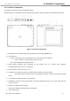
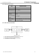
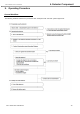
Figure 4.1. Detector Components
A. Wireless antenna: Transmits image data with wireless comunication (IEEE802.11n).
B. LED Indicators
• Ready: Lamp showing data communication state and ready state of the detector.
(Green: detector is ready / Orange: detector is busy)
• AP: Lamp indicating Wired / Wireless mode.
C. OLED Display: Displays some information for the detector such as a battery level, operating
modes(Wired/Wireless), HR / HT, and SSID ect.
D. Power Button: Turns the detector on / off.
E. AP Button: Can register the detector among the different wireless connection options.
(Connection options: Wireless using an AP/ Wireless using the detector’s internal AP/ Portable
mode).
F. X-ray Connector: Integrates with a x-ray generator.
G. Data/Power Connector: Data communication and power supplying through LAN or Power cable with the
circular connector.
H. Handle: Can grab the detector easily.
I. Battery Pack: Supplies electrical power to the detector.
J. Logo: A sticker logo.