
SRC-VX1P Sparted Vortex Pico VX1P User Guide


1
Vortex User Guide
Doc. V3.00 ©2004-2014
Spartan M
OVERVIEW
The Vortex flybarless range is based on a sophisticated hybrid rotor
control system that seamlessly combines mathematically accurate flybar
simulation with modern digital control algorithms. Combined with
Spartan’s market leading tail gyro technology the holding ability of the
Vortex is excellent and precise giving a very solid and dependable feel on
any size helicopter from tiny electrics to nitro and gas. The built in
governor responds exceptionally fast using Spartan’s pre-emptive
technology to provide power before the engine is bogged down. Finally,
the cutting-edge silicon ring MEMS (Micro Electrical Mechanical System)
sensors combined with adaptive digital filtering offer vibration immunity
tolerance not previously seen in RC helicopter controllers.
TROUBLESHOOTING, WARRANTY & REPAIRS
Should you encounter any problems, please do not return this product to
the store until you have carefully read this user guide, consulted the
knowledge base on the Spartan website and sought advice from our
technical support staff.
For repairs, servicing, technical support or questions regarding the
distribution of this product visit the support page at the Spartan website:
http://www.spartan-rc.com/
WARNING!
Model helicopters are not toys and have the potential to be very
dangerous. Failure to follow the safety precautions and warnings in this
user guide may result in severe injury to yourself and others. Beginners
are advised to seek further advice from an experienced adult pilot.
Read through the entire user guide and other associated documents
before operating this product.
This product contains chemicals known to the State of California to cause
cancer and birth defects or other reproductive harm.
Safety Precautions
BEFORE EACH FLIGHT:
• Verify that the Vortex operates correctly.
• Verify that the Vortex compensates in the correct direction.
• Verify that the Vortex is operating in the desired mode.
• Verify that the sensor mounting pads are in good condition.
• Verify that interconnection wires are not in contact with the sharp edges
of the helicopter frames.
• Verify that all linkages, ball links and blade grip bearings can move
freely without excessive friction.
GETTING STARTED
The Vortex is configured using a Spartan DataPod. Before you proceed
setting up your new Vortex please download the “DataPod User Guide for
Vortex” to familiarise yourself with the menu system navigation and other
DataPod related functions.
In order for the setup process to flow smoothly please ensure than you
apply power to the Vortex only as described below.
Using power from the ESC - Connect the ESC to the SV5 port of the
Vortex. Ensure that the motor wires are disconnected as some steps of
the setup process may cause the throttle signal to change activating the
motor without notice.
Using power from a separate BEC or battery
i)
Using satellite receivers - Connect the BEC or battery to the RX port
of the Vortex.
ii)
Using PPM, SBUS, XBUS, SUMD or similar receiver - Connect the BEC
or battery to the receiver’s battery input. Use the supplied heavy
duty male-to-male servo cable to connect the receiver’s output to
the RX port of the Vortex.
iii)
Using standard receiver - Connect the BEC or battery to the
receiver’s battery input. Use supplied heavy duty male-to-male servo
cable to connect the receiver’s collective pitch channel to the RX port
of the Vortex.
Any additional connections to receiver, servos and RPM sensor will be
performed at a later stage and guidance will be provided during the setup
process.
You are now ready to start installing your new Vortex. Please locate the
“Setup and Tuning Informtation” on the Spartan website and click on the
Setup tab. Follow the step by step instructions provided.
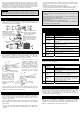
POWER BUS
OPERATION
Immediately after powering on, the Vortex performs automatic calibration
of the transmitter sticks and gyro sensor resting positions. During
calibration the sensor’s Status light alternates rapidly between red and
blue. The helicopter must remain undisturbed and the cyclic and rudder
sticks must be left at the centre position. Calibration lasts approximately
4 seconds and upon completion the Vortex will zip the swashplate and tail
rotor. The Status light should now be steady blue indicating a successful
calibration and that the helicopter is ready to fly.
The swashplate and tail will not zip if one of the following occurs:
• The RC receiver is not providing signal for all required channels.
• The battery alarm function detected low supply voltage.
• The Vortex flight computer is not receiving signal from the sensor.
• The sensor tests have not passed (sensor light will flash error pattern).
FIRST FLIGHT
Before your first flight with the Vortex:
Update the Throttle Failsafe of the Vortex as well as the one of your
radio system (if provided).
Set the Governor Rotor RPM even if you are not using the governor
function. Whilst this is not essential, knowledge of the approximate
rotor RPM (+/-100) allows the Vortex to optimise its rotor phase
compensation and vibration filtering algorithms.
Since the engine governor is not essential for the helicopter to fly we
advice that the governor is set to Off during the first flight and until the
tail, rotor and engine mixture are fine tuned.
Most flybarless systems benefit from firm head dampening. Soft or worn
out dampeners allow the rotor disk to flex excessively thus introducing a
control delay which ultimately results in degraded cyclic performance.
Your Vortex is designed to offer sharp cyclic stops which makes firm
dampening even more important. Check their condition now.
Ensure that any “play” in the rotor and tail system is kept to a minimum
and that the tail pitch linkages can move freely without excessive
friction through any guides, ball links or other joints.
Some parameters may require fine tuning during the initial flights.
Tail Gyro Gain
– The factory default value should provide enough
stability to at least hover; however you should always proceed with
care. If insufficient stabilisation or tail wag is seen the gain should be
raised or lowered respectively. It is not uncommon to find that the
optimal gain value for a helicopter could be as small as 25-45%. A small
value does not mean that the gyro will be limited in performance. Any
gain value performs well as long as it is the optimal gain value.
However, a gain below 25% indicates that the mechanical gain of the
tail is too high and therefore it is recommended to move the servo arm
ball link further in if possible. Similarly if 100% is reached and no tail
wagging is seen the ball link needs to be moved further out.
Rotor Gain
– The default value is a conservative estimate that should
suit a large number of helicopters. In some cases better performance
can be achieved by increasing the rotor gain. Adjust in small steps of 3-
5% and be aware that the helicopter may start to oscillate if the gain
becomes excessively high. If oscillations are seen do not increase the
gain further; reduce by a few percent until they are no longer present.
Governor Gain
– Due to the large variations in engine and fuel
performance it is expected that the governor gain may need to be
adjusted. If the engine is hunting (rapidly revving up and down) reduce
the gain until the hunting stops. Similarly, if the engine responds too
slowly to rapid changes of the collective pitch the governor gain will
need to be increased.
WARRANTY AND PRODUCT REGISTRATION
This product is warranted to be free from defects in materials or
workmanship for twelve months from the date of original purchase.
Within this period, Spartan RC will, at its sole option, repair or replace
any components which fail in normal use. Such repairs or replacement will
be made at no charge to the customer for parts or labour, provided that
the customer shall be responsible for any transportation costs. This
warranty does not cover failures due to wear and tear, abuse, misuse,
accident or unauthorized alterations or repairs. All warranty is return to
Vorte
x
All ports on this
side share (+) and
(-) lines. Power can
be applied to or
taken from any
port.
Special function
ports. Never
connect a battery
or other power
source on this
side on the unit.
All ports of the top
row share (+) and
(-) lines. Power can
be applied to or
taken from any
port.
Vorte
x
Nano
Special function
ports. Never
connect a battery
or other power
source at the
bottom row.