
Instruction manual

PRINTER’S INSTRUCTIONS:
INSTR,INSTL,IRE-5.0 • LINEAR P/N: 223116X20 • INK: BLACK •
MATERIAL: 20LB. GLOSS WHITE PAPER • SIZE: 4.250” X 17.500” FOLD TO 4.250” X 3.500”
• FOLDING: 5 PARALLEL FAN-FOLDS, FINISH WITH LOGO SHOWING • SCALE: 1-1
223116X20 • IMAGE 1
DESCRIPTION
The IRE-5.0 IR Blaster is a unique wand-shaped device containing
two very high output IR emitters. The Blaster wand is designed in
such a fashion as to allow the correct overhang (installer adjusted)
for control of a stack of A/V components. It can be mounted above
or below the components, or both, to ensure good coverage. It may
also be located up to 35 feet opposite the controlled equipment for
“across the room” operation, where conditions permit.
The dual emitters operate at different portions of the IR spectrum to
ensure robust operation of the widest range of IR controlled products.
Clear adhesive is used to mount the device, plus a small screw is also
provided to ensure no “drop-off”. The ILC-1.0 IR Collector can be used
to assist the IRE-5.0 Blaster in the control of stacked components,
where necessary. Refer to the ILC-1.0 Instructions.
ATTACHMENT
1. Arrange the components in the stack so that their front panels are
even, to prevent one shadowing the other. Also, make sure that
the front edges of any shelves are set back far enough to prevent
IR blocking.
2. Before mounting the IRE-5.0 Blaster permanently, hold (or tape
temporarily) in a position where the center of the curved surface
has a 1 to 2 inch overhang above the components (see Fig. 3)
.
Test and move the Blaster as necessary, until you have operation
of all components.
3. Clean the mounting spot on the cabinet surface of any waxes,
polishes, greasy substances, etc., before permanently mounting
the Blaster.
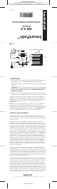
4. The IRE-5.0 has adhesive tape on its bottom surface. Peel the
protective layer off, exposing the adhesive (see Fig. 2)
.
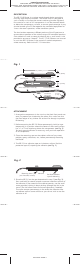
2-Conductor
3.5mm Plug
+
GND
8' Lead
(2.4m)
White Striped Side is Positive (+)
5/16" (8mm)
1/2" (13mm
)
3" (76mm)
Mounting Adhesive
Mounting Screw (included)
Dual Blaster Diodes
Mounting Slot
Fig. 1
Peel Back Protective
Layer for Mountin
g
Mounting Scre
w
(use if needed; see text)
Adhesive
Fig. 2
5. Place the IRE-5.0 on the spot determined in step 2 (see Fig. 3).
Press and hold for several seconds to ensure maximum contact of
the adhesive. If the material of the cabinet permits, use the small
screw provided, driving it about midway through the slot in the
wand. (The slot allows room for future adjustment, if needed).
The screw ensures permanency in the event the adhesive does
not adhere well on some surfaces or you do not wish to use the
adhesive at all.