
Installation Guide


3
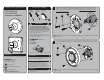
MEASURE
The Universal Valve Trim kit includes two (2) Spindle Adapters that allow for both shallow and
deep valve mount installations. Measure the distance between the front lip of the Wall Mounting
Plate and the end of the Symmons Spindle as shown below to determine which Spindle Adapter is
to be used.
• If the measurement falls between 9/16” to 1-1/16”, then Spline Adapter marked “B” is to
be used for installation.
• If the measurement falls between 1-1/16” to 1-9/16”, then Spline Adapter marked “A” is to
be used for installation.
A
B
4
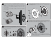
VERTICAL
LINE
Confirm that the Valve is in the off position. Retrieve Spline Adapter to be used as determined in
Step 3. Insert Spline Adapter (1) over Symmons spindle (2). One set of splines on the adapter must
be oriented perfectly vertical when installed, as shown below. Secure the Spline Adapter with the
8-32 X 7/8” Screw (3) provided.
5
RED
BLUE
Orient the Decorative Wall Plate (1) as shown below and insert the RED index button into the top
hole of the Wall Plate, and the BLUE index button into the lower hole. Slide Wall Plate Assembly
over Wall Mounting Plate (2).
6
Orient the Handle Assembly in a vertical position as shown below. Guide Handle Assembly onto
the Spline Adapter (3). While holding the Handle (1) stationary in the vertical position, thread the
Handle Escutcheon (2) onto the Wall Mounting Plate (4). Hand tighten until snug.
NOTE: This style of Valve uses a “Compression Stop”. After Handle Assembly
installation, rotate Handle clockwise to achieve full compression and closure of Valve.
If the Handle does not rest in a vertical position after full compression, repeat Steps 4
and 6 for proper Handle alignment.