
Installation Sheet
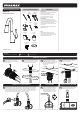

LEFT OR RIGHT
OF CENTER
10”-12”
16”-20”
DETERMINE MOUNTING LOCATION OF SOLENOID
8
Place the Solenoid Assembly against the
desired mounting surface while ensuring
adequate clearance for servicing of all
connections. If using the optional AC
Adapter, consider the distance to the
nearest electrical outlet. Solenoid Assembly
should be mounted so the inlet and outlet
ports are aligned vertically. Mark location of
Solenoid Assembly on the mounting
surface using a pencil, following the
dimensions shown.
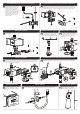
DETERMINE MOUNTING LOCATION OF SOLENOID (CONTINUED)
9
Remove Mounting Bracket from Solenoid Assembly. Using the previously marked location on
mounting surface, align Mounting Bracket horizontally to approximate position and mark the
mounting locations with a pencil. If mounting on drywall and not to stud, use appropriate anchors
and fasteners for application. Recommend included screw in easy anchor or equal for drywall.
MOUNTING SOLENOID
10
After securing the Bracket to the mounting surface, align and slide Solenoid Assembly over
Mounting Bracket.
11
CONNECT HOSE TO SOLENOID
Connect the Spray-head hose to the outlet
of the Solenoid. This is a push-to-connect
connection. Make sure to push the Hose
completely onto the Solenoid outlet fitting.
12
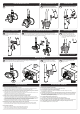
CONNECT SENSOR TO SOLENOID
Plug in Sensor Eye to Solenoid. Match up
the colors. Blue to Blue, Green to Green.
Ensure the White Stripe on the Male Plug
is aligned to the White Stripe on the
Female Plug.
A
B
INSTALL BATTERIES
13
Access the Interior Battery Enclosure by pressing down on the tab to release the tray holding the
batteries (A). Pull out Battery Tray (B). Insert or replace the batteries with six (6) new standard
1.5v AA batteries (C). Ensure the position of the new batteries are aligned to the plus (+) and
minus (-) symbols within the battery holder.
A
A
IF CONVERTING TO AC POWER (NON-INCLUDED OPTION)
14
Verify that no batteries are present within the battery enclosure (A). Connect the AC Adapter to the
Solenoid Body (B). Plug the AC Adapter into the wall outlet. The AC light (C) should illuminate.
15
SECURE BATTERY TRAY
Reinstall the Battery Tray. Make sure to
press the indicated location until the
battery door is fully seated and locks into
position.
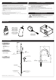
INSTALL WEIGHT
16
Use the provided screws to install the Weight onto the Spray-head Hose. Position the Weight
above the bottom of the Hose loop (recommended height is 19.5” to 21.5” below counter).
17
VERIFY PULL DOWN OPERATION
Pull down Spray-head and check for
smooth operation. Adjust weight and
routing of Spray-head Hose as needed.