
Installation Guide


INSTRUCTIONS FOR MODELS
92-SE-1200-1255-05
For additional assistance or service please contact:
SPEAKMAN
®
Company
400 Anchor Mill Road
New Castle, DE 19720
800-537-2107
customerservice@speakman.com
www.speakman.com
SE-1200
SE-1250
SE-1255
Combination Safety
Emergency Shower
and Eye/Face
Wash System
TOOLS AND SUPPLIES
Pipe
Wrench
Adjustable
Wrench
Strap
Wrench
Hex Key
Wrench
Mounting Hardware
(not included)
Level
3 year limited warranty.
Additional warranty information can be found at:
www.speakman.com
WARRANTY
MAINTENANCE
Cover your drain to prevent loss of parts. Be sure to
wear eye protection while cutting pipe.
SAFETY TIPS
IMPORTANT
ANSI Z358.1 requires that all safety emergency
equipment shall be activated on a weekly basis
to flush the line and verify proper operation.
SPEAKMAN furnishes a testing record tag
(91-0635) with each unit. On this tag, the date of
inspection and the inspector’s initials should be
noted. ANSI Z358.1 specifies that the height of the
spray heads is to be between 33” - 45” from the
floor. Use Thread Locker or Sealant on all threaded
connections. Be sure the Unit is level and plum.
Should you need parts to repair this unit, please
reference the parts listing for correct repair part number.
Before any maintenance is done, be sure to shut the
water supply off. Use only genuine SPEAKMAN parts
when repairing or replacing components. To order parts,
call 1-800-537-2107.
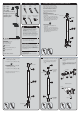
1
Front of Unit
*
1/2” Male
Threading
At desired location, mount Floor Flange
(13) on a flat, level surface using suitable
anchors, making sure that one of the three
ears on the Floor Flange is positioned at
what will be the front of the Stanchion.
The Unit should be placed so that there
is sufficient unobstructed area around
the Stanchion.
STANDARD INSTALLATION
• Assemble
1-1/4” x 32-3/8” Pipe (29) to Floor
Flange (13).
• Thread 1-1/4” x 1/2” Drain/Supply Cross
(12) onto Pipe (29). Side Outlets should face
the front and back of the Unit, and the 1/2”
male threaded outlet upward at 45° to the
right side of the Unit.
ADA INSTALLATION
•
1-1/4” x 26-7/16” Pipe (11) to Floor
Flange (13).
• Thread 1-1/4” x 1/2” Drain/Supply Cross
(12) onto Pipe (11). Side Outlets should face
the front and back of the Unit, and the 1/2”
male threaded outlet upward at 45° to the
right side of the Unit.
OR
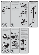
2
OR
STANDARD INSTALLATION
• Assemble 1-1/4” x 26-7/16” Pipe (11)
to Drain/Supply Cross (12).
• Assemble 1-1/4” Tee (10) to Pipe (11).
ADA INSTALLATION
• Assemble 1-1/4” x 32-3/8” Pipe (29)
to Drain/Supply Cross (12).
• Assemble 1-1/4” Tee (10) to Pipe (29).
Assure the Side Outlet portion of Tee (10)
is facing the rear of the Unit.
Rear of Unit
Front of Unit
*
3
• If water supply is coming from above Unit,
install Plug (7) into side outlet of Tee (10).
• If water supply is coming from behind
Unit, install Plug (7) into top outlet of
Tee (8).
Front of Unit
For Back Supply,
install Plug
(7) here.
For Top Supply,
install Plug
(7) here.
4
• Assemble 1” x 4-1/2” Pipe (6) into Side
Outlet of Tee (8). Review View 4a below
to understand the orientation of Ball
Valve (5).
• Assemble 1” Ball Valve (5) onto Pipe (6).
Valve Stops must be aligned correctly in
order for the Pull Handle to operate
properly.
Detail View 4a
To Shower Head
Valve Stops
To Shower Head
USE THREAD LOCKER OR SEALANT ON ALL THREADED CONNECTIONS