
Installation Manual


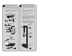


INSTRUCTIONS FOR MODELS
92-SE-6XX-01
For additional assistance or service please contact:
SPEAKMAN
®
Company
400 Anchor Mill Road
New Castle, DE 19720
800-537-2107
customerservice@speakman.com
www.speakman.com
Used for
Safety Shower
combination
stations:
SE-603
SE-616
SE-690
SE-693
SE-695
SE-697
TOOLS AND SUPPLIES
IMPORTANT
MAINTENANCE
The valve and the eye/face wash are the only portion
of the unit that may require maintenance. Should
you need parts to repair this unit, please contact
Speakman. Reference additional technical sheets
(supplied) for information on the eye/face wash, bowl
assembly, shower head, and shower activation valve.
Before any maintenance is done be sure to shut the
water supply off.
WARNING: Use only genuine Speakman parts when
repairing or replacing components.
To order parts call 1-800-537-2107.
ANSI Z358.1 specifies that the height of the spray
heads is to be between 33” - 53” from the floor.
Use Thread Locker or Sealant on all threaded
connections. Be sure the Unit is level
and plum.
Pipe
Wrench
Adjustable
Wrench
Strap
Wrench
Hex Key
Wrench
Not
Included
Level
OPERATION
SAFETY TIPS
Cover your drain to prevent loss of parts. Be sure to
wear eye protection while cutting pipe.
WARRANTY
Additional warranty information can be found at:
www.speakman.com
SHOWER OPERATION
The shower is activated by pulling the triangle pull
handle. Once the valve is activated the head will
continue to discharge water until the ring is released.
EYE/FACE WASH OPERATION
The eye/face wash is activated by pushing the push
handle back 90°. The unit will operate until the push
handle is manually pulled back up to the off position.
TESTING PROGRAM
ANSI/ISEA Z358.1 states that all safety emergency
equipment shall be activated on a weekly basis
to flush the line and verify proper operation.
Speakman Company furnishes a testing record tag
(91-0635) with each unit. On this tag the date of
inspection and the inspector’s initials should be noted.
1
Front of Unit
1/2” Male
Threading
• At desired location, mount Floor Flange
(13) on a flat, level surface using suitable
anchors, making sure that one of the three
ears on the Floor Flange is positioned at
what will be the front of the Stanchion.
• The Unit should be placed so that there
is sufficient unobstructed area around
the Stanchion.
• Assemble 1-1/4” x 29-3/8” Pipe (11)
to Floor Flange (13).
• Thread 1-1/4” x 1/2” Drain/Supply
Cross (12) onto Pipe (11). Side Outlets
should face the front and back of the Unit,
and the
1/2” male threaded outlet upward
at 45° to the right side of the Unit.