
Installation Sheet

INSTRUCTIONS FOR MODELS
92-SF-9700-9800-02
For additional assistance or service please contact:
SPEAKMAN
®
800-537-2107
customerservice@speakman.com
www.speakman.com
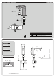
SF-9700
SF-9800
HELPFUL TOOLS & SUPPLIES:
TOOLS AND SUPPLIES
Adjustable
Wrench
Aerator
Wrench
(included)
3/8"
Wrench
Safety
Glasses
Warranty information can be found at:
www.speakman.com
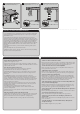
WARRANTY
FINISH MAINTENANCE
Cover your drain to prevent loss of parts. Be sure to
wear eye protection while cutting pipe.
SAFETY TIPS
IMPORTANT
• Be sure to read instructions thoroughly before
beginning installation.
• Do not over-tighten any connections or damage
may occur.
• This faucet has an operating range of 20-80 psi.
Your new Speakman Product is designed for years of
trouble-free performance. Keep it looking new by
cleaning it periodically with a soft cloth. The use of harsh
chemicals and abrasives may damage the finish and
void the product warranty. Please be sure to only use
approved cleaners. Please contact Speakman for any
clarification of acceptable cleaners.
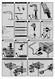
1
Remove the Rubber Wire Guard (1), Metal
Washer (2) and Mounting Nut (3) from the
threaded Shank.
2
Verify that the Rubber Gasket is in position and
aligned to the base of the Faucet.
3
Place the threaded shank and wire through the
mounting hole. Take extra precautions to avoid
pinching any wires. Lower Faucet into position.
4
OR
From beneath, install Rubber Wire Guard (1)
over the Shank and pass the Sensor Wires
through the Notch to prevent pinching of wires.
The Notch should be facing right. Install Metal
Washer (2) and Mounting Nut (3) onto Shank.
Align Faucet to desired position and wrench
tighten Mounting Nut (3). Verify that Sensor Wire
is not pinched.
5
Thread the Solenoid Outlet (2) directly onto
the Shank (1) by hand. Verify that the Rubber
Washer (3) is fully seated inside the swivel nut.
Hold Faucet in position and wrench tighten
the connection.
DRY CONNECTION ONLY.
DO NOT USE ANY SEALANT
ON THIS CONNECTION
6
Assemble "INLET" Supply Hose (1) (not supplied),
to the "INLET" connection (2) of Solenoid.
Wrench tighten.
DRY CONNECTION ONLY.
DO NOT USE ANY SEALANT
ON THIS CONNECTION
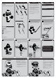
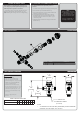
7
Make electrical connections from the Sensor Eye to the Solenoid Assembly. Connect the Blue Male Ended Wire
to the Blue Female Connection. Connect the Green Male Ended Wire to the Green Female Connection. To
further aid proper alignment, there are white alignment lines on the connector ends. These alignment lines
should face forward when properly installed.
GREEN
BLUE
8 FOR BATTERY MODEL (SF-9700)
Access the interior Battery Enclosure by pressing down on the tab to release the tray holding the batteries (1).
Pull out Battery Tray (2). Insert or replace the batteries with six (6) new standard 1.5v AA batteries. Ensure the
position of the new batteries are aligned to the plus (+) and minus (-) symbols within the battery holder.
9 FOR A/C MODEL (SF-9800)
Verify that no batteries are present within the battery enclosure (1). Connect the A/C Adapter to the Solenoid
Body (2). Plug the A/C Adapter into the wall outlet. The A/C light (3) should illuminate.