
Installation Guide

PAGE 2 10/13
92-3098 R-2
4) With the necessary opening(s) in the finished wall, assemble the accessory(s) to the rough piping (Important- See separate
“Accessory Installation Instructions” supplied with some of the accessories). With the rough-in template removed & the valve
turned OFF, turn both the hot & cold water supplies ON. Using the handle, operate the valve checking all the connections for
leaks.
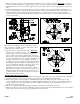
5) To limit the maximum hot water temperature the valve delivers, adjust the valve’s temperature limit stop (TLS) plate (See
Figure 3). Slip the retaining o-ring and the TLS plate towards the end of the spindle. Rotate the valve handle clockwise to the
maximum desired hot water temperature. Position the TLS plate so it contacts the lug on the valve bonnet and therefore
restricts the clockwise rotation of the handle. Slip the retaining o-ring back into the groove of the spindle. Turn off the valve
and remove the handle.
Note- For valve with built-in volume control/diverter feature,
make sure the brass “VC/DIV” spindle is in the center position
(spindle flats in the vertical position).
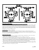
6) Slip the trim sleeve onto the spindle and valve. Important-
Rotate the sleeve so that the lug on the valve bonnet is in the pie
shaped opening of the sleeve (See Figure 4). Apply clear
silicone sealant to the backside outer flat surface of the wall
plate. For valve with a brass wall plate, make sure the threaded
boss in the wall plate is below the center hole. Carefully slip the
wall plate onto the trim sleeve and “VC/DIV” spindle (If
applicable). Properly position against the finished wall. Fasten
the wall plate to the valve using the (2) long wall plate screws.
Do not over tighten the wall plate screws. Wipe off any excess
sealant from around the outer edge of the wall plate. If
applicable, remove clear protective sheet from top of index
plate. Slip the index plate over the trim sleeve and fasten to the
wall plate with the screw & flat washer provided. Properly
position the handle onto the valve spindle and screw into place.
Push index button into the handle.
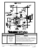
BACK-TO-BACK INSTALLATION
On this type of installation, the balancing/regulating cartridge must be rotated 180° on the valve on which the hot & cold inlets are
reversed. Refer to Figure 5 on the next page for the proper positioning of the balancing/regulating cartridge.
1) Make sure the hot & cold water supplies are shut OFF. With the valve in the OFF position, remove the (4) valve bonnet
screws. Carefully remove the bonnet. Remove the balancing/regulating cartridge from the valve body by pulling on the valve
spindle or the blue cap of the cartridge. Make sure the lower rubber quad rings (2) are properly installed in bottom of the
cartridge and not in the valve body.
2) Reposition the balancing/regulating cartridge per the Figure 5 drawing. Push cartridge into valve body.
3) Make sure the large bonnet o-ring seal is installed and seated properly in the valve body. Reassemble the valve bonnet, making
sure the “UP” on the bonnet is in the up position. Tighten the (4) bonnet screws.