
Installation

INSTRUCTIONS FOR MODELS
92-STW-350-01
For additional assistance or service please contact:
SPEAKMAN
®
Company
400 Anchor Mill Road
New Castle, DE 19720
800-537-2107
customerservice@speakman.com
www.speakman.com
STW-350
Thermostatic Mixing Valve
HELPFUL TOOLS & SUPPLIES:
TOOLS AND SUPPLIES
Level Measuring
Tape
Safety
Glasses
Pencil
Flat Tip
Screwdriver
Adjustable
Wrench
Pipe
Wrench
Thread Seal
Tape
• Lockable shut-off on the outlet supply if tempered
water is supplied to one or more emergency fixtures.
• Lockable shut-off on the inlets/supplies.
• Unions on all connections to facilitate removal of
valve.
IMPORTANT
• Compliance and conformity to local codes and
ordinances is the responsibility of the installer.
• Valve should be accessible for testing, adjustment
and maintenance in the installed position.
• Make sure that all water supply lines have been
flushed and then completely turned off before
beginning installation. Debris in supply lines can
cause valves to malfunction.
• Ensure the mounting structure and mounting
hardware can safely support the product in use.
• Do not over-tighten any connections or damage
may occur.
• Be sure to read instructions thoroughly before
beginning installation.
• Installers shall verify that no single emergency
fixture supplied by this device has a minimum
flow rate less than 3.0 GPM (11.4 L/min).
NOTE: Valve must be installed with check valves.
If shut off valves are installed in the supply line
for maintenance purposes, provisions shall be
made to prevent unauthorized shut off.
Be sure to wear eye protection.
SAFETY TIPS
Warranty information can be found at:
www.speakman.com
WARRANTY
See section “Testing the Mixing Valve”.
MAINTENANCE
IMPORTANT
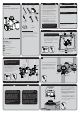
1A INSTALLING INTO CABINET
WARNING: The Valve will not function in the way it is intended to if Cold water supply pipe is
connected to "H" Inlet on Valve and Hot water supply pipe is connected to "C" inlet on Valve.
Connect Supply Lines and Fixtures.
• Ensure incoming water supplies are turned OFF.
• Apply Thread Seal Tape to Inlet and Outlet pipe
threads in a clockwise manner.
• Install Inlet and Outlet connections to the valve
as shown. Wrench Tighten.
NOTE: If installing into Cabinet see installation
manual provided with it before proceeding.
X3
HOT
INLET
COLD
INLET
TEMPERED WATER
OUTLET
Connect Supply Lines and Fixtures.
• Ensure incoming water supplies are turned OFF.
• Apply Thread Seal Tape to Inlet and Outlet pipe
threads in a clockwise manner.
•
Install the COLD Inlet pipe to the “C” Inlet on Valve.
•
Install the HOT Inlet pipe to the “H” Inlet on Valve.
• Install Outlet connection to the Valve.
• Wrench tighten connections.
X3
NOTE:
• If not installing into Cabinet, the Valve can be
installed vertically with either the inlets at the top
(as shown), or the inlets at the bottom
depending on the location of inlet water
supplies.
HOT
INLET
COLD
INLET
TEMPERED
WATER
OUTLET
HOT
INLET
COLD
INLET
TEMPERED
WATER
OUTLET
1B INSTALLING WITHOUT CABINET
WARNING: The Valve will not function in the way it is intended to if Cold water supply pipe is
connected to "H" Inlet on Valve and Hot water supply pipe is connected to "C" inlet on Valve.
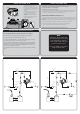
2
• Check for leaks by pressurizing the unit SLOWLY.
• Check the temperature when approx. 10 GPM
water flow is reached (equivalent to two (2)
eye/face washes) and adjust if necessary.
• When the Check Stops are in the fully open
(operating) position, the Stem will align with
the Stem Nut.
OPEN
CLOSE
STEM
NUT
CHECK STOP
STEM
HOT
INLET
COLD
INLET
TEMPERED WATER
OUTLET
CAUTION
2: When maintaining and
adjusting the Mixing Valve, the
delivered flushing fluid
temperature shall be in the tepid
range as per ANSI/ISEA Z358.1
Standard. In circumstances where
chemical reaction is accelerated
by flushing fluid temperature,
a medical advisor should be
consulted for the optimum
temperature for each application.
1: When maintaining and
adjusting the Mixing Valve, all
fixtures should be isolated from
use. Speakman recommends
that appropriate personnel
shall work safely at all times
and in a manner consistent
with the OSHA Lock/Tag out
standard, 29 CFR 1910.147
and other applicable
standards.
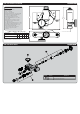
3 SETTING THE MIXING VALVE
This Mixing Valve has been set at the factory to
deliver 85 °F outlet flow. High temperature limit is
set to 90 °F by design. Should the Valve require
adjustment, or an application require a different set
temperature, proceed as follows:
Adjust Temperature with Water Running
• Check the temperature when approximately
10 GPM water flow is reached (equivalent to
two eye/face washes).
• Contact proper medical and safety authorities
to determine the correct water temperature for
the specific application (i.e., chemicals).
• Remove the Plastic Cap (White) from the Valve
using a Flat Tip Screwdriver.
REMOVE THE CAP WITH
FLAT TIP SCREWDRIVER
FROM THE NOTCH
ON THE CAP