HTSD10X 10X Pan-Tilt Speed Dome Camera Please read this manual thoroughly before operation and keep it handy for further reference.
CONTENTS Warning & Caution 3 What’s in the Box? 3 General Features Names of Each Part 4 5 Installation A. Connection Methods 6 B. Ceiling Mount Type 7 C. Embedded Mount Type Quick Operating Keys Diagnostic 8 9 OSD Menu Setting A. OSD Menu Table 10 B. DOME SET 11 C. CAMERA SET 16 D. PRESET 18 E. AUTO SCAN 19 F. TOUR SET 20 G. PRIVACY SET 21 H. PATTERN SET 22 I. ALARM SET 23 J. SECTOR SET 24 DIP Switch Setting A. ID Setting (DIP SW1) 25 B.
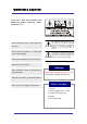
WARNING & CAUTION If you fail to read this information and handle the product incorrectly, serious injury may occur. Never install the product in area exposed to oil or gas. Never install the product on a ceiling that cannot hold its weight. This symbol is intended to alert the user to the presence of un-insulated “dangerous voltage” within the product’s enclosure that may be of sufficient magnitude to constitute a risk of electric shock to persons.
GENERAL FEATURES 100X Zoom Mini Speed Dome Quick Operation Keys 10X Optical Zoom with 10X digital zoom This camera provides quick functional keys in order to be easily controlled by any controller or DVR. ±0.02° dome system accuracy With 0.
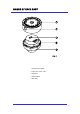
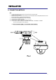
NAMES OF EACH PART 1. Surface Mount Adaptor 2. Cap Screw ( PT3/4 , 2EA ) 3. Dip Switch 4. Terminal Block 5.
INSTALLATION A. CONNECTION METHOD A-1 1. 2. 3. 4. 5. 6. Loosen the screws on the domes cover and remove it from the base. (Screws will not come out) Loosen the screws which connect the mount cover and Main base and separate the dome cover from the main base. (Screws will not come out) Connect power (12 VDC 1.5 A ) to Power and GND. Connect video to Video and GND. Connect communication cable to RS-485 connectors. Connect alarm cable to GND like 1 and GND, 2 and GND, 3 and GND, 4 and GND.
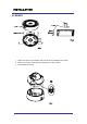
INSTALLATION B. MOUNT 1. Attach the surface mount adaptor with 4 screws at the installation site. (FIG.4) 2. When you use pipe, please note the standard size of pipe. (FIG.5) 3. Re-assemble the domes.
QUICK OPERATING KEYS 1-64 + preset and 101~200 + preset are used for preset and 65-100 + preset used for functions. For example, to enter OSD MENU, press the button 95 +PRESET.
QUICK OPERATING KEYS DIAGNOSTIC When the Power is turned on a DIAGONOSTIC is operated. The following messages are displayed on the monitor. CAMERA ID : 001 BAUD RATE : 2400 BPS WAITING……… A. PAN ORIGIN CHECK OK TILT ORIGIN CHECK OK TX CONNECTION TEST OK CAMERA COMM TEST OK Pan Origin Test Zero point of Pan is founded after Panning test. B. Tilt Origin Test Zero point of Tilt is founded after Tilting test. C.
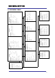
EXIT SECTOR ALARM PATTERN PRAVACY TOUR AUTO SCAN CAMERA SET DOME SETUP MAIN MENU ALARM SET PRIVACY SET SAVE EXIT : 01 PRESET NO DWELL TIME : 10 EXIT : 01 PRESET ID: OFF/ON SECTOR ID: OFF ON COORDINATE:ON/OFF [SYSTEM STATUS] [INITIALIZATION] [PREVIOUS PAGE] [PREVIOUS PAGE] CAMERA ID: OFF/ON OSD DISPLAY EXIT SAVE DATA FILL EXIT SAVE ALARM ACT ALARM INPUT ALARM NO.
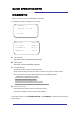
OSD MENU SETTING To enter the OSD Menu, press the button 95 + PRESET. MAIN MENU DOME SETUP CAMERA SET AUTO SCAN TOUR PRAVACY PATTERN ALARM SECTOR EXIT * Use the joystick “up - down” to move the position and “left - right” to make selection B. Dome Setup To enter the Dome setup, move the joystick right to move the cursor. DOME SET CAMERA ID : CAM1□□□□□□□□□□□□ RECOVER : OFF MANUAL SPEED : 100°/S AUTO FLIP : OFF ZOOM SPEED : FAST ALARM : DISABLE LANGUAGE : ENGLISH [NEXT PAGE] SAVE AND EXIT EXIT B-1.
OSD MENU SETTING B-2. DOME SET - RECOVER This feature allows the dome to work from the last setting before you use the dome manually (Auto scan, group tour, pattern or sectors) , after the set time, even power shut down and it turns on again. Recovery time can be programmed from 15 second to 90 seconds. The default setting is OFF. B-3. DOME SET - MANUAL SPEED Manual Speed of Pan/Tilt is selectable from 10°/sec up to 200°/sec. The default setting is 100°/sec B-4.
OSD MENU SETTING B-8-2. DOME SET – [NEXT PAGE] – [PASSWORD] To enter this page to set a password, move the joystick to the right direction. The password must be set by preset number from 001 to 255 (Default 99) A. OSD MAIN MENU TABLE (PAGE 11) The default setting is BLANK. ENTER PASSWORD BY ENTERING PRESET CODE PASSWORD *** CONFIRM *** Press any number from 001~255 with the preset button on password blank and again to confirm.
OSD MENU SETTING OSD DISPLAY CAMERA ID : PRESET ID : SECTOR ID : COORDINATE : [PREVIOUS PAGE] OFF OFF OFF ON DEFAULT SETTING B-8-4. DOME SET – [NEXT PAGE] – [SYSTEM STATUS] This page shows the information of this camera. SYSTEM STATUS PROTOCOL : BAUD RATE : FIRMWARE VER. : UPGRADED DATE : CAMERA MODULE : [PREVIOUS PAGE] PELCO D, P 2400 BPS 2.00 06.
OSD MENU SETTING - To clear memorized data, move joystick to the right direction when cursor is on each item. TOUR CLEAR TOUR CLEAR ARE YOU SURE? YES NO Press FOCUS NEAR button when the cursor is at YES in order to clear memorized data. Then each item such as tour, preset, sector and so on is displayed on the monitor about 2~3 seconds. After this process, the menu is returned to the previous page. * [PRESET CLEAR], [SECTOR CLEAR], [PRIVACY CLEAR], [PATTERN CLEAR] are same as [TOUR CLEAR].
OSD MENU SETTING C. CAMERA SET CAMERA SET FLICKER MIRROR APERTURE D ZOOM WB MODE PIC FLIP BLC D/N MODE DSS MODE EXIT : : : : : : : : : OFF OFF 10 OFF AWB MODE OFF OFF AUTO OFF C-1. CAMERA SET - FLICKERLESS Flickerless feature is selected between 50Hz and 60Hz. The default setting is OFF (NTSC: 60Hz / PAL: 50Hz). Set flicker mode ON when power source is in discord with frequency. The default setting is OFF C-2. CAMERA SET - MIRROR This feature creates a mirror image. The default setting is OFF. C-3.
OSD MENU SETTING C-6. CAMERA SET – PIC FLIP Picture flip feature turns ths picture upside down. Move the joystick to the right or left direction to select OFF/ON. The default setting is OFF. C-7. CAMERA SET – BLC (Back Light Compensation) The default setting is OFF and BLC modes can be OFF/ON. OFF – Backlight compensation is not activated. ON – Back light compensation is activated. This function can be recalled by pushing 93 + preset button. C-8.
OSD MENU SETTING D. PRESET SET To enter PRESET SET, move the joystick to the right direction. PRESET SET PRESET NO :001 PRESET ID :PRESET001------PAN :XXX.XX TILT : XXX.XX SAVE EXIT D-1. DEFAULT SETTING PRESET – PRESET NO. Up to 164 numbers of preset positions are available. Move joystick to the right or left direction to select a preset no. D-2. PRESET – PRESET ID To set preset ID, select up to 16 characters using Joystick to the left or right.
OSD MENU SETTING E. AUTO SCAN SET * 66 + preset button is working as AUTO SCAN after setting. AUTO SCAN SET START ANGLE END ANGLE DIRECTION ENDLES SPEED DWELL TIME SAVE AND EXIT EXIT : : : : : : XXX.X.XX.X XXX.X.XX.X CW OFF 10°/S 03 DEFAULT SETTING E-1. AUTO SCAN – START ANGLE To set the start angle, press FOCUS FAR button then move the joystick to the starting angle which is to be memorized. Press FOCUS FAR button again is to escape. E-2.
OSD MENU SETTING F. TOUR SET 8 Programmable tours can be set and each tour is available to set up to 64 preset steps. After setting the data to each tour group, 71~78 + preset buttons are working as group tour # 1~8 TOUR SET TOUR NO TOUR TITLE TOUR STEP PRESET NO. DWELL TIME SPEED SAVE EXIT : : : : : : 01 TOUR01□□□□□□□□□□ 01 01 03 200°/S DEFAULT SETTING F-1. TOUR SET – TOUR NO. Max. 8 group tour no. set by the joystick are available. F-2.
OSD MENU SETTING G. PRIVACY SET 4 Privacy masking zones are available to block out areas of the scene. PRIVACY SET PRIVACY NOMBER : 01 DISPLAY : OFF ACTION : MOVE SAVE EXIT DEFAULT SETTING G-1. PRIVACY SET – PRIVACY NUMBER. Up to 4 privacy masking zones are available. G-2. PRIVACY SET – DISPLAY. Move joystick to the right or left direction to set ON in order to show the selectable block in the center of the monitor. This block appears as a translucent blue square when turned ON.
OSD MENU SETTING H. PATTERN SET 8 programmable patterns are available with 16 characters of title. After setting the data to each pattern # 1~8, 81~88+ preset buttons are working as Pattern # 1~8. PATTERN SET PATT NO : 01 PATT TITLE: PATTERN01□□□□□□□ DATA FILL : 0% SAVE EXIT DEFAULT SETTING H-1. PATTERN SET –PATT NO. Up to 8 programmable user-defined patterns set by the joystick are available. H-2.
OSD MENU SETTING I. ALARM SET 4 Alarm inputs are available and each alarm can activate presets, group tours or patterns. ALARM SET ALARM NO : 01 ALARM INPUT: OFF ALARM ACT : 001 SAVE EXIT DEFAULT SETTING I-1. ALARM SET – ALARM NO. Up to 4 alarms are selectable by using the joystick to the right when the cursor is on ALARM NO. I-2. ALARM SET – ALARM INPUT Input alarm provides two different ways - NC (Normal Close) or NO (Normal Close) I-3.
OSD MENU SETTING J. SECTOR SET Up to 8 programmable sectors are available with 16 characters. This feature is useful to memorize certain locations such as a parking zone, etc. When a camera goes through this area, it shows the letter you memorized. SECTOR SET SECTOR SECTOR SECTOR SECTOR SAVE EXIT Start Position NO : 01 ID: SECTOR01□□□□□□□□ START: XXX.X.XX.X END : XXX.X.XX.X End Position DEFAULT SETTING J-1. SECTOR SET – SECTOR NO. Up to 8 programmable sectors set by the joystick are available. J-2.
DIP SWITCH SETTING A-1. DIP SW SETTING This Speed Dome camera provides up to 63 camera ID’s, adjustable using the 1st~6th Dip switch. Open the camera case to set ID using DIP SW1. * Factory default: Camera ID = 1, PELCO-D Termination Baud rate Protocol ID Set A-2.
DIP SWITCH SETTING A-3. PROTOCOL 7th~8th dip switches are used for Protocol Setting. Factory Default: Pelco-D or Pelco-P ( Auto detection) DIP SW1- 7 DIP SW1- 8 OFF OFF Pelco-D or Pelco-P A-4. BAUD RATE SETTING The 9th Dip Switch is used for BAUD RATE setting. DIP SW can be changeable to 2400bps, 9600bps. Factory Default: 2400bps. DIP SW1 9 th BAUD RATE OFF 2400 ON 9600 . A-5. 485 TERMINATIONS 10th Dip Switch is used for 100Ω termination.
TROUBLE SHOOTING If you have trouble operating in your camera, refer to the following. PROBLEM SOLUTION Not operating Check if the power supply is 12 VDC. Check if RS-485 communication cable is connected correctly. Check camera ID setting. Check the termination. No picture Check if all the cables are connected correctly. Check if the monitor is adjusted correctly. Check if video signal line is cut. Dark screen Adjust the monitor.
SPECIFICATIONS MODEL PAN /TILT HTSD10X Pan Rotation Angle Manual Pan Speed Preset Tilt Rotation Angle Manual Tilt Speed Preset System Accuracy Presets Group Tour FUNCTIONS POWER OTHERS Auto scan Pattern Privacy Zone Sector Password Protection Alarm Input Alarm Actions Auto Flip OSD Menu Communication Protocol Power Consumption Power Supply Construction Dimensions Weight Motor Type Micro Steps Storage Temperature Operating Temperature Certifications Image Sensor Total NTSC Image PAL Pixels Number Of
DIMENSIONS 29
MEMO 30
Rev.100125 Speco Technologies is constantly developing product improvements. We reserve the right to modify product design and specifications without notice and without incurring any obligation.