4- & 8- Channel Digital Video Recorder WARNING RISK OF ELECTRIC SHOCK DO NOT OPEN WARNING: TO REDUCE THE RISK OF ELECTRIC SHOCK, DO NOT REMOVE COVER (OR BACK). NO USER-SERVICEABLE PARTS INSIDE. REFER SERVICING TO QUALIFIED SERVICE PERSONNEL. The lightning flash with arrowhead symbol, within an equilateral triangle, is intended to alert the user to the presence of uninsulated "dangerous voltage" within the product’s enclosure that may be of sufficient magnitude to constitute a risk of electric shock.
Operation Instruction Important Safeguards 1. Read Instructions All the safety and operating instructions should be read before the appliance is operated. 10. Overloading Do not overload wall outlets and extension cords as this can result in the risk of fire or electric shock. 2. Retain Instructions The safety and operating instructions should be retained for future reference. 11.
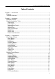
4- & 8- Channel Digital Video Recorder Table of Contents Chapter 1 ─ Introduction ................................................................................................ 1 Features...................................................................................................................... 1 Technical Overview .................................................................................................... 1 Chapter 2 ─ Installation ......................................................
Operation Instruction Copy Button .......................................................................................................... 11 Play/Stop Button ................................................................................................... 12 Turning on the Power ............................................................................................... 12 Initial Unit Setup .......................................................................................................
4- & 8- Channel Digital Video Recorder Playing Recorded Video ........................................................................................... 65 Searching Video ....................................................................................................... 66 Search Menu ........................................................................................................ 67 Event Log Search ..............................................................................................
Operation Instruction List of Illustrations Figure 1 ─ Typical DVR installation. ......................................................................................... 2 Figure 2 ─ 8-Channel DVR rear panel. ..................................................................................... 3 Figure 3 ─ DVR front panel. ..................................................................................................... 7 Figure 4 ─ Infrared remote control...............................................
4- & 8- Channel Digital Video Recorder Figure 49 ─ Speco Remote setup screen. .............................................................................. 47 Figure 50 ─ Notification Callback setup screen. ..................................................................... 47 Figure 51 ─ Notification Mail setup screen. ............................................................................ 48 Figure 52 ─ Notification SNS setup screen. ...............................................................
Operation Instruction viii
4- & 8-Channel Digital Video Recorder Chapter 1 ─ Introduction Features Your color digital video recorder (DVR) provides recording capabilities for four or eight camera inputs.
Operation Instruction Your DVR can be set up for event or time-lapse recording. You can define times to record, and the schedule can change for different days of the week and user defined holidays. The DVR can be set up to alert you when the hard disk drive is full, or it can be set to record over the oldest video once the disk is full. Your DVR uses a proprietary encryption scheme making it nearly impossible to alter video. You can view video and control your DVR remotely by connecting via Ethernet.
4- & 8-Channel Digital Video Recorder Chapter 2 ─ Installation Package Contents The package contains the following: Digital Video Recorder Power Adaptor and Power Cord Operation Instruction (This Document) Speco Central Software CD and Operation Instruction Infrared Remote Control Required Installation Tools No special tools are required to install the DVR. Refer to the installation manuals for the other items that make up part of your system. Figure 2 ─ 8-Channel DVR rear panel.
Operation Instruction Audio In/Out Your DVR can record audio from up to four sources. Connect the audio sources to Audio In 1, Audio In 2, Audio In 3 and Audio In 4 as needed using RCA jacks. Connect Audio Out to your amplifier. NOTE: It is the user’s responsibility to determine if local laws and regulations permit recording audio. NOTE: The DVR does not have amplified audio output, so you will need a speaker with an amplifier.
4- & 8-Channel Digital Video Recorder Alarm Input/Output NOTE: To make connections on the Alarm Connector Strip, press and hold the button and insert the wire in the hole below the button. After releasing the button, tug gently on the wire to make certain it is connected. To disconnect a wire, press and hold the button above the wire and pull out the wire. Alarm In 1 to 8 (Alarm-In): You can use external devices to signal the DVR to react to events.
Operation Instruction Connector Pin Outs: Master Unit RX → TX → GND → To To To → → → Slave Unit TXD RXD GND NOTE: Refer to the following for pin-out details for the 9-pin connector of the slave unit. Male Female Pin 2 Pin 3 Pin 5 RXD (Receive Data) TXD (Transmit Data) GND (Ground) Power Cord Connector Connect the connector from the adaptor to the DVR, and connect the AC power cord to the adaptor and then to the wall outlet. WARNING: ROUTE POWER CORDS SO THAT THEY ARE NOT A TRIPPING HAZARD.
4- & 8-Channel Digital Video Recorder Chapter 3 ─ Configuration NOTE: Your DVR should be completely installed before proceeding. Refer to Chapter 2 ─ Installation. Front Panel Controls Figure 3 ─ DVR front panel. Menu Button Play/Stop Button Play/Pause Button USB Port Copy Button Camera Buttons HDD LED Esc Button Arrow Buttons Power LED The front panel looks and operates much like a VCR combined with a multiplexer. The following describes each button and control.
Operation Instruction Copy Button Pressing the COPY button allows you to copy video clips. Esc Button During menu setup, pressing the ESC button closes the current menu or setup dialog box. Play/Stop Button Pressing the PLAY/STOP button enters the playback mode, and pressing the button again exits the playback mode. When entering the playback mode, video is paused. Pressing the (Play/Pause) button plays back video at regular speed.
4- & 8-Channel Digital Video Recorder Power LED The POWER LED is lit when the unit is On. USB Port A USB port on the front panel is provided to connect external hard disk or flash drives for video clip copying or system upgrades. Position external drives close enough to the DVR so that you can make the cable connections, usually less than 6 feet. Use the USB cable provided with the hard disk drive to connect it to the DVR. A USB mouse (not supplied) can be connected to the USB port.
Operation Instruction ID Button If a DVR System ID is set to 0, the infrared remote control will control that DVR without any additional operations. (Refer to the System Information setup screen in this chapter for further information on setting the System ID.) If the system ID is 1 to 16, you must to press the ID button and then press the number button (1 to 16 (+10 & 6)) in order to control that DVR.
4- & 8-Channel Digital Video Recorder Stop: Pressing the button stops playback and enters the Live Monitoring mode. Backward: When in the pause mode, pressing the button moves to the previous image. Forward: When in the pause mode, pressing the button moves to the next image. In the Live Monitoring mode, pressing any playback button enters to the Search mode. Alarm Button Pressing the ALARM button resets the DVR’s outputs including the internal buzzer during an alarm.
Operation Instruction Play/Stop Button Pressing the PLAY/STOP button enters the playback mode, and pressing the button again exits the playback mode. When entering the playback mode, video is paused. Pressing the button plays back video at regular speed. The screen displays when the DVR is in the Pause mode and the screen displays when the DVR is playing back video. Turning on the Power Connecting the power cord to the DVR turns on the unit. The unit takes approximately 60 seconds to initialize.
4- & 8-Channel Digital Video Recorder NOTE: To log the user out of the system, press the MENU button on the front panel or move the mouse pointer to the top of the screen and then select (Logout) in the Live Monitoring menu. The Logout screen displays asking you to confirm whether or not you want to log out the current user. Figure 6 ─ Logout screen. Setup Screen Figure 7 ─ Setup screen.
Operation Instruction System Setup Figure 8 ─ System menu. Information Highlight Information in the System menu and press the appears. button. The Information setup screen In the Information screen, you can name the site location, assign a System ID number, select the language the screens are displayed in, display software version number, upgrade the software, show the System Log, display recorded time data, and clear all data. Highlight the Site box and press the button.
4- & 8-Channel Digital Video Recorder Highlighting the Install button and pressing the button will install the selected software package. Highlighting the Cancel button and pressing the button will close the window without upgrading the software. If the upgrade package file is not installed on the DVR properly, you will get an error message. CAUTION: The system restarts automatically after completing the upgrade, and it takes approximately one minute to restart.
Operation Instruction Highlight the box beside File name and press the button. A virtual keyboard allows you to enter the file name. Selecting Export will save the log information in .txt file format on the USB device. NOTE: When opening the saved .txt file, setting to the proper character encoding and using fixed width fonts will be required to read the file properly. The box beside Recorded Data – From / To displays the time information of recorded data.
4- & 8-Channel Digital Video Recorder Highlight the Holiday tab, and the Holiday setup screen appears. You can set up holidays by highlighting + and pressing the button. The current date appears. Highlight the month and day and change them by using the Up and Down arrow buttons. Press the button to add the date. Dates can be deleted by highlighting the beside the date and pressing the button. Figure 11 ─ Holiday setup screen.
Operation Instruction The information in the Type column describes the storage device. The capacity of the storage device is displayed in the Capacity column. The Format column displays whether the device is used for recording (Record) or not (Not Using). Not formatted indicates the device is not formatted. Figure 13 ─ Storage Information setup screen. Highlight the box in the Format column for the desired storage device and press the button. You will be able to format the device for recording.
4- & 8-Channel Digital Video Recorder The Type column displays the type of storage device. The Disk Bad column displays the percentage of bad sectors. Not formatted – The device is not formatted. Good – Less than user-defined percentage of bad disk sections is damaged. Bad – More than user-defined percentage of bad disk sections is damaged. Figure 14 ─ Storage Status setup screen. The Temperature column displays the temperature of the storage device.
Operation Instruction Highlighting a Group Name and pressing the assigned to the group. button allows you to change the authority levels CAUTION: Write down the new password and save it in a secure place. If the password is forgotten, the unit must be reset using the Factory Reset Button and all data settings will be lost. Highlighting a User Name and pressing the button allows you to add or change the password assigned to that user. You can also change the group to which the user is assigned.
4- & 8-Channel Digital Video Recorder PTZ Setup – The user can establish all PTZ settings on a local system or a PC running Speco Central. Alarm-Out Setup – The user can establish all Alarm-Out settings on a local system or a PC running Speco Central. Covert Camera Setup – The user can establish all Covert Camera settings on a local system or a PC running Speco Central. Record Setup – The user can establish all Record settings on a local system or a PC running Speco Central.
Operation Instruction If you selected the EZ Record, selecting the Next button starts the EZ Record. Figure 17 ─ EZ Record screen. Date/Time Setup Date: Set the system date and select the date format. Time: Set the system time and select the time format. Time Zone: Select your time zone. The Time Zone can be selected on the map. Enable Daylight Saving Time: Selecting the box sets the system to use daylight saving time.
4- & 8-Channel Digital Video Recorder NOTE: The recording resolution will be set to Very High when selecting High Video Quality Priority Profile, High when selecting Standard Recording Profile, and Standard when selecting Longer Recording Time Priority Profile. NOTE: The recording quality and recording speed of each camera channel will be set as shown below according to the Record Method and Record Video Quality you set.
Operation Instruction LAN Setup Select between Auto Configuration and Manual Configuration for network configuration, and then select the Test button to test the network configuration you selected. NOTE: Selecting Auto Configuration allows the DVR to automatically obtain LAN parameters (IP address, Gateway, Subnet Mask and DNS Server address). Selecting Manual Configuration allows you to set up LAN parameters manually.
4- & 8-Channel Digital Video Recorder Select the Finish button to finish the EZ Setup. Shutdown Highlight Shutdown in the System menu and press the button. The Shutdown screen displays asking you to confirm whether or not you want to shut the system down. After selecting Shutdown and pressing the button, a screen will appear telling you when it is safe to disconnect power. Figure 19 ─ Shutdown screen. Recording Setup Figure 20 ─ Record menu.
Operation Instruction NOTE: The total ips of all camera channels will be limited to 120 ips (60 ips for 4-ch Model) when set to High resolution and 60 ips (30 ips for 4-ch Model) when set to Very High resolution. NOTE: When set to High or Very High resolution, the maximum recording speed of each camera channel might decrease so as not to exceed the total ips of all camera channels. The 8-channel model DVR has two camera groups (No. 1: cameras 1 to 4 and No.
4- & 8-Channel Digital Video Recorder Highlighting Use Panic Recording and pressing the button toggles between On and Off. Figure 22 ─ Panic Record setup screen. Highlight the Panic Recording – Duration box and set the duration of panic recording. Panic recording will stop automatically after the preset duration as long as (Panic) in the Live Monitoring menu is not selected to stop the panic recording. You can set the dwell from 5 minutes to 1 hour.
Operation Instruction Highlight the Schedule Mode box and press the button. You can select between Simple Mode and Advanced Mode. Selecting Advanced Mode allows you to set up individual recording schedule for each event. Highlight the + and press the button to add a schedule item. Highlight the box under the Day heading and press the button to change the days that the scheduled recording will take place. Choose from: Sun, Mon, Tue, Wed, Thu, Fri, Sat, M~F, Hol and All.
4- & 8-Channel Digital Video Recorder NOTE: Day, Range and Channels that are not defined will use the setting values of the previous schedule item. NOTE: When more than two schedule items are registered in the same day and time range, the DVR will follow the latest registered schedule item.
Operation Instruction NOTE: When the DVR is in the Time or Time & Event mode, it ignores the pre-event settings and follows the time settings. Event Setup Figure 26 ─ Event menu. Alarm-In Highlight Alarm-In in the Event menu and press the button. The Alarm-In setup screen appears. The alarm terminal strip on the back of the DVR has inputs associated with each alarm. You can set up each input on the Alarm-In screen.
4- & 8-Channel Digital Video Recorder You can set the actions the DVR will take whenever it senses an input on one of its alarm input connectors. Highlight the desired box under the Record heading, and press the button. A list of cameras appears. Select the cameras that you want the DVR to record whenever it detects an input on the associated alarm input. Figure 28 ─ Alarm-In Actions 1 setup screen.
Operation Instruction Motion Detection Highlight Motion Detection in the Event menu and press the setup screen appears. button. The Motion Detection Your DVR has built-in video motion detection. Video motion detection can be turned On or Off for each camera. Figure 30 ─ Motion Detection Settings setup screen. Highlighting the box under the Sensitivity heading and pressing the button allows you to adjust the DVR’s sensitivity to motion for Daytime and Nighttime independently.
4- & 8-Channel Digital Video Recorder You can adjust the minimum number of detection blocks that must be activated to trigger a motion alarm. Highlighting the box under the Min. Blocks heading and pressing the button allows you to adjust the minimum number of detection blocks for Daytime and Nighttime independently. Smaller numbers provide greater sensitivity because fewer detection blocks must be activated. Turning Zone View On will allow you to observe how the DVR is reacting to motion.
Operation Instruction NOTE: For the Alarm-Out action, the alarm output and beep you select should be set to the Event mode in the Alarm-Out setup screen (Schedule tab). Highlight the box under the Notify heading and press the button. You can toggle the entire list On and Off by highlighting Notification and pressing the button. You can toggle the individual items On and Off by highlighting that item and pressing the button. Highlight OK and press the button to accept your changes.
4- & 8-Channel Digital Video Recorder The DVR can be set to react to video loss differently for each camera. Each camera can be associated with another camera, trigger an Alarm-Out connector, sound the DVR’s internal buzzer, notify a number of different devices, and/or move PTZ cameras to preset positions. Figure 34 ─ Video Loss Actions setup screen. Highlight the box under the Record heading and press the button. A list of cameras appears. You can associate as many cameras with that camera as you wish.
Operation Instruction The DVR checks to see if anything is blinding the camera. Figure 35 ─ Video Blind Settings setup screen. Highlighting the box under the Sensitivity heading allows you to adjust the DVR’s sensitivity to video blind for Black and White independently from 0 (Never) and 1 (least sensitive) to 15 (most sensitive). NOTE: Video blind might NOT be detected for a camera with a very noisy image especially when set for low sensitivity values.
4- & 8-Channel Digital Video Recorder Highlight the box under the Alarm-Out heading and press the button. Select between Alarm Output and Beep (DVR’s internal buzzer) that you would like to activate and to sound whenever the DVR detects video blind on the selected camera. NOTE: For the Alarm-Out action, the alarm output and beep you select should be set to the Event mode in the Alarm-Out setup screen (Schedule tab). Highlight the box under the Notify heading and press the button.
Operation Instruction Highlight Setup…, and press the button. Use the ATM or POS manufacturer’s recommended settings when configuring the RS232, RS485, USB-Serial or LAN ports. Highlight the box beside Text-In Product, and press the button. Select your device from the list. NOTE: The following description is for a Generic Text Device. The screen changes for different types of text input devices, and there will be different parameter boxes for you to enter information.
4- & 8-Channel Digital Video Recorder The DVR can be set to react to text input. Text input can be associated with cameras, trigger an Alarm-Out connector, sound the DVR’s internal buzzer, notify a number of different devices, and/or move PTZ cameras to preset positions. Figure 39 ─ Text-In Actions setup screen. Highlight the box beside Record and press the button. A list of cameras appears. You can associate as many cameras with the Text Input as you wish.
Operation Instruction The DVR can be configured to run selfdiagnostics and report the results. Highlighting the box beside System and pressing the button allows you to select the interval that you want the DVR to run selfdiagnostics on the system. You can select from 1 hr. to 30 days or Never. Figure 40 ─ Health Check setup screen. Highlight the Setup... box beside Check Recording and press the button. The Check Recording screen appears.
4- & 8-Channel Digital Video Recorder Highlight the second box beside Disk Temperature, and press the (Fahrenheit) or ºC (Celsius), and press the button. button. Select either ºF Highlight the Actions tab and the System Event Actions setup screen displays. The DVR can be set to react to system events. System events can activate the Alarm-Out connector, sound the DVR’s internal buzzer, and/or notify a number of different devices. Figure 42 ─ System Event Actions setup screen.
Operation Instruction The Event Status screen displays the status of the DVR’s systems and inputs. Events will be highlighted, and related channels or events will flicker for five seconds when detected. Alarm-In, Motion, Video Loss, Video Blind and Text-In will be highlighted when each event is detected based on the settings you made in the Alarm-In, Motion Detection, Video Loss, Video Blind and Text-In setup screen on the Event menu. Figure 43 ─ Event Status setup screen.
4- & 8-Channel Digital Video Recorder Highlight the first box beside Remote Watch – Transfer Speed. Press the Up and Down arrow buttons to set the Transfer Speed from 50Kbps to 100Mbps. Highlight the second box beside Remote Watch – Transfer Speed. You can select the unit of measure for the transfer speed between: bps and ips. Press the button to set the transfer speed. Figure 45 ─ Network setup screen.
Operation Instruction Highlight the box beside Type and press the button. You can select the type of network configuration from: Manual, DHCP and ADSL (with PPPoE). Select the desired type and press the button. Selecting Manual from the Type allows you to set up LAN parameters manually. Figure 46 ─ LAN (Manual) setup screen. Change the numbers by highlighting them and using the Up and Down arrow buttons to increase or decrease the number. The factory default LAN settings are: IP Address: 192.168.1.
4- & 8-Channel Digital Video Recorder CAUTION: When changing the port settings, you must change the port settings on the PC running Speco Central as well. Refer to the Speco Central Operation Instruction for details. Selecting DHCP from the Type and highlighting Save button reads the current IP address of the DVR configured by DHCP (Dynamic Host Configuration Protocol) network. Highlight Auto (Default) and press the button to toggle between On and Off.
Operation Instruction NOTE: You will need to get the IP Address or domain name of the DVRNS Server from your network administrator. NOTE: You can use the domain name instead of IP address if you already set up the DNS Server when setting up the LAN. Highlight the box beside Port and press the button. Set the port number of the DVRNS server using the Up and Down arrow buttons to increase or decrease the numbers. Highlight Enable NAT and press the button to toggle between On and Off.
4- & 8-Channel Digital Video Recorder NOTE: Selecting Use Mobile sets the recorded image resolution to Standard automatically regardless of your Record settings. NOTE: Selecting Use Mobile sets the remote watch quality to Basic automatically regardless of your Network – Remote Watch settings. NOTE: Selecting Use Mobile sets the Speco Remote service to be enabled automatically regardless of your Speco Remote settings.
Operation Instruction Highlight the box beside Retry and enter the number of times you would like the DVR to try contacting the computer. You can select from 1 to 10 retries. Highlight the Mail tab, and the Mail setup screen displays. The DVR can be set up to send an email when an event occurs. The Mail account can be turned On or Off by highlighting the boxes under the No. heading and pressing the button. Highlight the + and press the a mail recipient.
4- & 8-Channel Digital Video Recorder Highlight the box beside Port and press the button. Use the arrow buttons to enter the SMTP Server port number obtained from your system administrator. The default port number is 25. Highlight Enable SSL/TLS and press the button to toggle between On and Off. When it is On, the DVR can send an email via an SMTP server requiring SSL (Secure Sockets Layer) authentication. Highlight the box beside Authentication and press the Authentication screen appears. button.
Operation Instruction Highlight the Schedule tab, and the Schedule setup screen displays. You can add and edit notification schedules on this screen. Highlight the + and press the button to add a schedule. Highlighting the boxes under the Column heading and pressing the button allows you to edit the information in those boxes. The Day box allows you to select the days that the notification schedule will be active. The choices are: Sun, Mon, Tue, Wed, Thu, Fri, Sat, M~F, Hol and All.
4- & 8-Channel Digital Video Recorder You can turn the camera number On or Off, and you can change the Title of each camera using the virtual keyboard. You can also determine which cameras will display on the monitors by selecting Normal, Covert 1 or Covert 2 from a drop-down list in the Use column. NOTE: When selecting the Covert 1, the DVR displays the camera title and status icons on the covert video. When selecting the Covert 2, the DVR displays only camera title on the covert video.
Operation Instruction Configure the port’s setting based on the PTZ camera manufacturer’s instructions. Audio Highlight Audio in the Devices menu and press the button. The Audio setup screen appears. The DVR can record up to four audio inputs. Highlight the box beside the input and press the button. A list of cameras appears, and you can select which camera you want associated with that audio input. Highlight Enable Audio-Out and press the button. This toggles between enabling and disabling audio out.
4- & 8-Channel Digital Video Recorder You can add and edit alarm output schedules on this screen. Highlight the + and press the button to add a schedule. Highlighting the boxes under the Column heading and pressing the button allows you to edit the information in those boxes. The Day box allows you to select the days that the alarm schedule will be active. The choices are: Sun, Mon, Tue, Wed, Thu, Fri, Sat, M~F, Hol and All. Figure 59 ─ Alarm-Out Schedule setup screen.
Operation Instruction You can select the audio files associate with each event. Highlight the box under the Associated Audio and press the button. A list of audio file name appears, and you can select which audio file you want to associated with that event. You can import saved audio files or export the current audio files. To import saved audio files, connect the USB device containing the audio file (.aaf or .wav) to the DVR. Highlight Digital Deterrent – Import… and press the button.
4- & 8-Channel Digital Video Recorder NOTE: Any audio file used for Digital Deterrent should be named “Sound_1” to “Sound 16.” (Not Case Sensitive) Display Highlight Display in the Devices menu and press the button. The Display screen allows you to select what information will be displayed on the monitor. Highlighting an item and pressing the button toggles that item On and Off. When an item is On, there is a checkmark in the box beside it.
Operation Instruction Highlight the box beside Mode and press the button. You can select between Full Sequence and Cameo Sequence. (8-ch Model Only) Figure 62 ─ Main Monitor setup screen. Selecting (Sequence) in the Live Monitoring menu causes the DVR to sequence cameras, and the DVR can sequence cameras in two modes: “Full” and “Cameo”. In the Full mode, the DVR sequences through the cameras and displays them full screen.
4- & 8-Channel Digital Video Recorder Highlighting OK and pressing the button applies resolution changes. Remote Control Highlight Remote Control in the Devices menu and press the button. The Remote Control setup screen allows you to select a port and make correct settings for a remote keyboard. Highlight the box beside Port and select between None, RS232 and RS485. If the RS232 port and RS485 port is in use for PTZ control, networking or text input, the remote keyboard cannot be configured.
Operation Instruction 58
4- & 8-Channel Digital Video Recorder Chapter 4 ─ Operation NOTE: This chapter assumes your DVR has been installed and configured. If it has not, please refer to Chapters 2 and 3. The DVR’s controls are similar to a VCR. As with a VCR, the main functions are recording and playing back video. However, you have much greater control over recording and playing back video. You can establish recording schedules based on time of day and day of the week.
Operation Instruction NOTE: The Live Monitoring menu also can be displayed by moving the mouse pointer to the top of the screen. Live Monitoring Menu Display Selecting (Display Menu) in the Live Monitoring menu displays the following Display Menu. Camera: Selecting Camera and choosing the camera number displays the selected camera full screen.
4- & 8-Channel Digital Video Recorder Sequence Selecting (Sequence) in the Live Monitoring menu causes the cameras to display sequentially. When in one of the multiview formats, selecting Sequence will cause the DVR to go through predefined screen layouts (Full Sequence). Or, the bottom, right screen will display live cameras sequentially (Cameo Sequence).
Operation Instruction Digital Deterrent Selecting (Digital Deterrent) in the Live Monitoring menu displays the following setup screen and allows the DVR to play manually. Highlight the box beside Source name and press the button to select the source file to play. Highlighting Trigger plays the selected file as the digital deterrent. Panic Selecting (Panic) in the Live Monitoring menu starts panic recording of all cameras, and displays on the screen. Selecting again stops panic recording.
4- & 8-Channel Digital Video Recorder Zoom Mode You can enlarge an area of the video by selecting (Camera Menu) Zoom in the Live Monitoring menu. For a few seconds after selecting (Camera Menu) Zoom from the Camera, a rectangle displays on the screen. A rectangle shows the area that will be enlarged. You can move the rectangle around using the arrow buttons. Pressing the (Play/Pause) button in the Zoom mode enlarges the area in rectangle.
Operation Instruction Select the PTZ camera you wish to control. The icon flickers on the PTZ camera screen. To use the remote control buttons, press the Left and Right arrow buttons to pan left and right. Press the Up and Down arrow buttons to tilt the camera up and down. Press the ZOOM + button to zoom in, and press the ZOOM – button to zoom out. You can use the FOCUS and FOCUS buttons to focus the image. You can establish preset positions for PTZ cameras.
4- & 8-Channel Digital Video Recorder Recording Video Once you have installed the DVR following the instructions in Chapter 2 ─ Installation, it is ready to record. The DVR will start recording based on the settings you made in the Record setup screen. See Chapter3 ─ Configuration. Recycle On or Recycle Off. The factory default is Recycle On. It does this by recording over the oldest video once the hard disk is full. Setting the DVR to Recycle Off causes it to stop recording once the hard disk is full.
Operation Instruction Camera Buttons: Pressing the individual camera buttons will cause the selected camera to display full screen. Arrow Buttons: Pressing the button plays video backward at high speed. Pressing the button again toggles the playback speed from , and . Pressing the button plays video forward at high speed. Pressing the button again toggles the playback speed from , and . When in the pause mode, pressing the button moves to the next image and pressing the button moves to the previous image.
4- & 8-Channel Digital Video Recorder NOTE: The Search menu also can be displayed by moving the mouse pointer to the top of the screen. Search Menu Display Selecting (Display Menu) in the Search menu displays the following Display Menu. Camera: Selecting Camera and choosing the camera number displays the selected camera full screen. It is the same as pressing the individual camera buttons on the front panel or clicking the left mouse button on a camera image when in one of the multiview formats (i.e.
Operation Instruction Export Selecting (Export) in the Search menu displays the following Export menu. See the following Clip Copy section for details. EZ Copy: Selecting EZ Copy will set the starting point of the video to be clip copied, and the icon displays at the bottom-left corner of the screen. Selecting EZ Copy again will set the ending point of the video to be clip copied and displays the Clip-Copy screen.
4- & 8-Channel Digital Video Recorder Panic Selecting (Panic) in the Search menu starts panic recording of all cameras, and selecting again stops panic recording. Data Source Selecting (Data Source) in the Search menu allows you to select the data source to be searched. Selecting Record searches recorded data on primary storage installed in the DVR, and selecting Other searches recorded data on storage used for another DVR then installed in this DVR.
Operation Instruction Highlight the box beside To and press the button to toggle between On and Off. When set to Off, you can enter a specific Date and Time. When set to On, the search will be to the last recorded image. Highlight the box beside Check Time Overlap and press the button. It toggles between On and Off. You will only be able to turn the Check Time Overlap on or off if a user-defined date and time is set to From and To.
4- & 8-Channel Digital Video Recorder Record Table Search Recording information about video images currently displayed on the screen displays on the recording status bar. A grey vertical line indicates the current search position. To search specific video, move the vertical line by using the Left or Right arrow buttons on the front panel or by clicking the mouse on the desired segment. < Compact View > < Standard View > < Expanded View > Figure 70 ─ Record Table Search screen.
Operation Instruction Selecting located at the bottom displays the Search menu. Go to: Displays the first or last recorded image, or searches by date and time (see the previous Searching Video – Go To section of this chapter for more details). Clip-Copy: Clips a video segment and saves it (see the following Clip Copy section for more details). Digital Deterrent Recording: Extracts audio files from recorded audio on the DVR (see Chapter 3 – Configuration – Digital Deterrent section for more details).
4- & 8-Channel Digital Video Recorder You can search video from the first to last recorded images, or you can set the start and stop times and dates. Highlight the box beside From and press the button to toggle between On and Off. When set to Off, you can enter a specific Date and Time. When set to On, the search will be from the first recorded image. Highlight the box beside To and press the button to toggle between On and Off. When set to Off, you can enter a specific Date and Time.
Operation Instruction Text-In Search The DVR maintains a log of each time there is Text Input. The Text-In Search screen displays this list. Use the arrow buttons to highlight the event for which you would like to see video. Pressing the (Play/Pause) button will extract the video associated with the Text Input and display the first image of the event. Pressing the button will start playing the “event” video segment. Pressing PLAY/STOP button returns to live monitoring. Figure 72 ─ Text-In Search screen.
4- & 8-Channel Digital Video Recorder Highlighting the + and pressing the button allows you to add a new set of search parameter. Set up the desired search parameter. Refer to the Appendix – Text-In Search Examples for further information on setting up search parameters. The column can be used to delete a set of search parameter or entire sets of search parameters. Highlight Case Sensitive and press the button. This will toggle between On and Off.
Operation Instruction Highlight the box beside Password and press the button. A virtual keyboard appears allowing you to enter the password for reviewing the video clips. Highlight the box beside Dest. and press the you would like to record the video clip. button. You can select the storage device on which CAUTION: The USB device for clip copy must be FAT 16 or FAT32 format. The DVR automatically assigns a file name to the video clip. However, you can give the video clip file a different name.
4- & 8-Channel Digital Video Recorder Appendix USB Hard Disk Drive Preparation Preparing the USB hard disk drive in Windows 2000 NOTE: Preparing a USB hard disk drive under Windows XP, Windows Vista and Windows 7 is almost identical to Windows 2000. 1. 2. 3. 4. Connect the USB hard disk drive to your computer using the USB Cable. Turn on your computer. The USB device icon should display on the Taskbar.
Operation Instruction 12. Right click the newly created hard disk drive icon and select “Format”. 13. In the Format Screen, select “Full” as the “Format type” and click “Start”. 14. After formatting is complete, connect the USB hard disk drive to the DVR. Text-In Search Examples Search Example I 1 2 3 4 5 6 123456789012345678901234567890123456789012345678901234567890 Item Unit price Qty amount ================================================== Coke | $ 2.20 | 1(s) | $ 2.20 Fanta | $ 2.20 | 1(s) | $ 2.
4- & 8-Channel Digital Video Recorder Search Example II 1 2 3 4 5 6 123456789012345678901234567890123456789012345678901234567890 Item Unit price Qty amount ================================================== Coke | $ 2.20 | 1(s) $ 2.20 Fanta | $ 2.20 | 1(s) $ 2.20 Hotdog | $ 3.50 | 3(s) $ 10.50 Pepsi | $ 1.95 | 1(s) $ 1.95 ================================================== total : $ 16.
Operation Instruction Computer system requirements for using the Speco Remote program are: Operating System: Microsoft® Windows® XP x86 (32 Bit) (Service Pack 3), Microsoft® Windows® Vista x86 (32 Bit) (Service Pack 1), Microsoft® Windows® 7 x86 (32 Bit) CPU: Intel Pentium III (Celeron) 600MHz or faster RAM: 128MB or higher VGA: 8MB or higher (1024x768, 24bpp or higher) Internet Explorer: Version 6.0 or later Start Internet Explorer on your local PC.
4- & 8-Channel Digital Video Recorder NOTE: There might be a problem with screen display or screen update due to low image transmission speed when using the Microsoft Windows Vista or higher operating system. In this situation, it is recommended you disable the Auto Tuning capability of your computer. Run the Command Prompt with elevated administrator permissions (Go to the Start Menu Accessories Command Prompt Click the right mouse button and select the Run as administrator option).
Operation Instruction ⑨ Click the to control alarm out devices at the remote site. Click the to set up the image drawing mode and OSD display. You can adjust the display speed by changing the image drawing mode, and select OSD information to be displayed on the screen. ⑪ Click the to save the current image as a bitmap or JPEG file format. ⑫ The event status window at the bottom displays a list of events that were detected from the remote site.
4- & 8-Channel Digital Video Recorder Click the to log out the Speco Remote program. Click the to access to the web monitoring mode. ③ Position the mouse pointer on the WebSearch logo to see the version of the Speco Remote program. ④ The DVR information window displays the time information of recorded data on the remote DVR and login information of Speco Remote. ⑤ Click the to blur, sharpen, equalize and interpolate playback images. Click to zoom out or zoom in the recorded image.
Operation Instruction Click the to save any video clip of recorded data as an executable file, or click the to save the current image in a bitmap or JPEG file format. Click the to print the current image on a printer connected to your computer. ⑫ Click the to reload the recording data. ⑬ The timetable displays recorded data of the selected camera by time (in hour segments). ⑭ Selecting a camera on the screen and clicking the right mouse button displays the text menu screen.
4- & 8-Channel Digital Video Recorder Error Code Notices No. 0 1 2 3 4 100 101 102 103 104 105 300 301 302 303 304 400 401 402 500 System Upgrade Related Description No. Unknown error. 0 File version error. 1 Operating system version error. 2 Software version error. 3 Kernel version error. 4 Upgrade device mounting failed. 5 Package is not found. 6 Extracting package failed. 7 LILO failed. 8 Rebooting failed. 9 Invalid package. 10 Remote connection failed. 11 Remote network error.
Operation Instruction Map of Screens 86
4- & 8-Channel Digital Video Recorder Specifications Playback/Record Speed (images per second) VIDEO NTSC or PAL (Auto Detect) Composite: 4 or 8 inputs, 1 Vp-p, auto-terminating, 75 Ohms Composite: 1 BNC, 1 Vp-p, 75 Ohms VGA: 1 (Auto Detect) Composite: 720x480 (NTSC), 720x576 (PAL) VGA: 800x600, 1024x768, 1280x1024@60Hz 8-ch Model: 240ips (NTSC), 200ips (PAL) @ CIF (Full Duplex) 4-ch Model: 120ips (NTSC), 100ips (PAL) @ CIF (Full Duplex) Alarm Input Alarm Output Internal Buzzer Network Connectivity Audi
Operation Instruction Dimensions (W x H x D) Unit Weight Shipping Weight Shipping Dimensions (W x H x D) Operating Temperature Operating Humidity Power Power Consumption Approvals GENERAL 10.4" x 2.0" x 7.5" (265mm x 52mm x 191mm) 3.7 lbs. (1.7kg) 7.3 lbs. (3.3kg) 14.0" x 4.1" x 13.4" (355mm x 103mm x 340mm) 41°F to 104°F (5°C to 40°C) 0% to 90% 8-ch Model: 12V , 1.2A (Adaptor: 100-240 V~, 50/60Hz, 1.5A, 12V , 5A) 4-ch Model: 12V , 1.2A (Adaptor: 100-240 V~, 50/60Hz, 1.0A, 12V , 3A) Max.