6 CHANNEL NETWORK READY DVR DVR-16/IP User’s Manual
Precautions z z z z z z z z z z z z z z z z z All the safety and operation instructions should be read before the DVR-16/IP is operated. All the safety and operation instructions should be retained for future reference. Comply with operating instruction and notice warning information. Do not use strong or abrasive detergents when cleaning the DVR-16/IP. There are no user-serviceable parts inside. Contact qualified service personnel for maintenance.
CONTENT 1. Features .................................................................................................................................. 5 2. DVR-16/IP Application............................................................................................................ 5 3. Quick Installation Guide ........................................................................................................ 6 4. Front Panel Introduction .............................................................
6.5.1.1 Day Start Time/ Day Stop Time................................................................. 20 6.5.1.2 Day REC PPS/ Night REC PPS ............................................................... 20 6.5.1.3 Day REC Quality/ Night REC Quality........................................................ 20 6.5.2 Weekend............................................................................................................. 20 6.5.2.1 Weekend Setting ....................................................
6.7.1 RS-485 ID Set Up ............................................................................................... 26 6.7.2 RS-485 Baud Rate.............................................................................................. 26 6.7.3 Software Information........................................................................................... 26 6.7.4 HDD Information ................................................................................................. 26 6.7.5 Shutdown............
1. Features z z z z z z z z z z z z z z z z z z z z Powerful Wavelet compression Proprietary real time O.S.
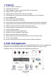
3. Quick Installation Guide The DVR-16/IP is equipped with a mobile rack, the HDD is hot-swappable. You can exchange the HDD when the HDD is full. The following figures illustrate how to install HDD into the removable cartridge. Step1: Pull the active-handle outwards and unlock with the miniature key provided (Figure 1). Step2: Pull the handle outwards till the carrier body is out of the cartridge (Figure 1). Step3: Push the release latch to slide the top cover backwards and remove it (Figure 1).
4. Front Panel Introduction The DVR-16/IP front panel controls enable you to perform preset and programmable functions. The figures below show the available buttons on the front panels. **DVR-16/IP starts detecting the camera and recording automatically after power is on. 4.1 The Buttons on the Front Panel The following are the introductions of DVR-16/IP front panel buttons. The front panel is illustrated and each button is described by name and function. CHANNEL 1~16 1.
MENU Press this button to enter OSD setup menu (the LED will be lit). ENTER / ZOOM 1. In OSD menu mode, this button is used to make the selection or save settings. 2. In full-screened mode, this button functions as a “2x2 Zoom In” button (the LED will be lit). DIRECTION 1. These buttons function as directional control in OSD menu. 2. In Zoom mode, press these buttons to view the wanted viewing area. 3.
SET In multi-windows display mode, press this button to enter SET mode. The menu will appear with the cursor over the first window. Use DIRECTION buttons to move the cursor, then press the CHANNEL button to assign the camera directly. The cursor will move to next window automatically. Press ESC button to exit SET mode. MODE Press this button to select display formats (4, 5, 7, 9,10,13 and 16 windows). The camera LEDs of selected cameras should be lit.
5.
Day / Night Switch 6-1 No Day 60 1 Day / Night SW Enable 2 Switch 3 Delay For Active 4 Exit Event Response 6-2 1 Internal Buzzer 2 Event Relay Output 3 Event List 4 Event Full Screen 5 Call Event Display 6 Response Duration 7 Any Key To Stop 8 Exit ON ON ON OFF ON 10 ON Motion Detect 1 2 3 4 6-3 Motion Detect Configuration Table 2 Condition Set Up Exit OFF Camera_1 MAIN MENU 1 2 3 4 5 6 7 8 9 10 11 Event List OSD / Timer Monitor Camera Record Event Others Save / Load Default CD-RW Engineer
Software Information 1 CPU Filename 2 FPGA Filename 3 Date 4 Video System 5 DSP BD HW 6 DSP BD SW 7 Exit D6SE0100 FPGA0505 2003/01/23 NTSC SK1V3302 SK1V3300 HDD Information Others 7 1 RS-485 ID Setup 2 RS-485 Baud Rate 3 Software Information 4 HDD Information 5 Shutdown 6 Exit 224 9600 1 HDD Size 2 Free Size 3 Total Rec Time 4 Free Rec Time 5 Begin 6 End 7 Exit 7-3 7-4 40GB 17GB 7Hr ----Hr 2003/04/22 16:39 2003/04/23 11:12 Shutdown 7-5 1 Shutdown: No 2 Shutdown: Yes 3 Exit Load Installer Setti
6. OSD Menu Setup The OSD menu is composed in hierarchy architecture, it allows you to configure the DVR-16/IP according to the applictation enveironment. Many options can be selected via the operation of the OSD menu. To enter this OSD menu, press the MENU button of the front panel, then the OSD menu will appear with a highlight cursor over the first item. The cursor can be moved by the up and down buttons.
6.2.4 Date/ Time Position This item allows you to move current Date/ Time Display to any position. Use the DIRECTION buttons to move Date/ Time display. 6.2.5 PB Date/ Time Position This item allows you to move the recorded Date/ Time Display to any position. 6.2.6 RS-485 Time Calibration RS-485 is used for multi-point communications: many devices can be connected to the same bus. Move to this item and press the ETNER button, all DVR-16/IP timers will be synchronized. 6.2.
6.3.2 Live Refresch Rate This item allows you to setup the camera refresh rate on the Main monitor; use right/ left buttons to select “Fix” or “Auto”. “Fix” means each camera has the same refresh rate. “Auto” means the camera with more motion will get higher refresh rate automatically. 6.3.3 Screen Center Point This item allows you to move the center point of the main monitor. Use the DIRECTION buttons to pan/ tilt the monitor center point. Press ESC button to exit when finished. 6.3.
6.4.1.1 Install This item allows you to install each channel on 1 Configuration Table1. Every channel is “installed” by default; you may uninstall any one of them manually. Once a channel is un-installed, all related functions are disabled (√ = camera installed; • = camera not installed). 6.4.1.2 Covert This item allows you to make each camera’s input invisible (covert) on both main and call monitor, while DVR-16/IP keeps recording the camera’s video.
◆ PELCO Speed Dome PELCO Speed Dome DVR-16/IP is capable of connecting to PELCO Speed Dome; the related settings can be adjusted here in this sub-menu. You can pan/ tilt PELCO Speed Dome by pressing SET and the direction buttons simultaneously after you are entering this sub-menu. 1 Protocol Setup 2 ID Setup 3 Zoom 4 Focus 5 Bfightness 6 Set Preset Point 7 Goto Preset Point 8 Enter Speed Dome Menu 9 Exit D_Type 1 Protocol Setup There are two Protocol types to choose from: D_type and P_type.
Goto Preset Point Press right/ left direction button to select the number of the wanted preset point; then press Enter to go to the selected preset point. Set Group Dwell Press the right/ left direction button to choose a proper dwell time. Go Preset Group Press Enter to start sequencing. Stop Preset Group Press Enter to stop sequencing. 6.4.1.4 Termination This item allows you to enable/ disable the terminal resister of each camera.
Situation 1: No alarm event happens. Channel 1 PPS = 30 * 4 = 6.31 4 +1+1+1+1+1+1+1+1+1+1+1+1+1+1+1 Channel 2 PPS = 30 * 1 = 1.58 4 +1+1+1+1+1+1+1+1+1+1+1+1+1+1+1 Channel 3 PPS = 30 * 1 = 1.58 4 +1+1+1+1+1+1+1+1+1+1+1+1+1+1+1 Situation 2: An alarm event happens on channel 2. Channel 1 PPS = 30 * 4 = 4.61 4 + 8 +1+1+1+1+1+1+1+1+1+1+1+1+1+1 Channel 2 PPS = 30 * 8 = 9.23 4 + 8 +1+1+1+1+1+1+1+1+1+1+1+1+1+1 Channel 3 PPS = 30 * 1 = 1.15 4 + 8 +1+1+1+1+1+1+1+1+1+1+1+1+1+1 6.4.
HDD size 40 GB 80 GB 120 GB 160 GB Quality: Ultra 5 10 15 20 Total Record Time (Hour) Quality: Super Quality: High Quality: Normal 7 9 12 14 18 24 21 27 36 28 36 48 6.5.1 Day/ Night Quality: Low 15 30 45 60 Day / Night This menu allows you to setup the Day start/ stop time, the PPS (Picture Per Second) and recording quality for Day and Night time. 6.5.1.
6.5.3 REC Event Only You are allowed to decide the situation DVR-16/IP starts recording. If you select “OFF”, then DVR-16/IP will remain in recording mode all the time. If you choose a time, then DVR-16/IP starts recording only when an event (both Alarm and Motion events) is triggered, and the time you choose indicates how long DVR-16/IP keeps recording. For example, if you select “15 sec”, DVR-16/IP starts recording when an event is triggered, and it keeps recording for 15 seconds. 6.5.
6.5.6 Rec Priority Mode This item allows you to set up the record priority, use RIGHT/LEFT keys to select Setup or Auto. Setup means priority mode will follow the setup value in configuration table, Auto means the camera with most motion will get higher priority automatically. 6.5.7 Circular Record The DVR-16/IP can store the recorded video information in circular or not. If the setting is “ON” (default), the earliest recorded video will be over-written automatically (none-stop recording).
6.6.1.3 Delay For Active After the Day/ Night switch setting has changed, there is a delay time before the event process takes effect; this function is to avoid the operator triggering a false event by mistake. 6.6.2 Event Response Event Response This sub-menu allows you to set how the DVR-16/IP responds to the triggered event. 1 Internal Buzzer 2 Event Relay Output 3 Event List 4 Event Full Screen 5 Call Event Display 6 Response Duration 7 Any Key To Stop 8 Exit ON ON ON OFF ON 10 ON 6.6.2.
6.6.2.7 Any Key To Stop When the event is triggered, the buzzer will beep, the Alarm Out relay will be activated. If you want to stop these actions by pressing any one key, then you must select “YES” for this item. 6.6.3 Motion Detect Motion Detect This menu allows you to configure how Motion Detection works. Each camera can have its “Detect Area” and “Sensitivity” defined individually. 1 Motion Detect 2 Configuration Table 2 3 Condition Set Up 4 Exit OFF 6.6.3.
6.6.3.5 Sensetivity This item allows you to setup the threshold of motion detection. The first bar shows the current detected amount of motion of this camera. The second and third bar allows you to setup the “day/ night threshold” (or “trigger level”), once the detected motion amount become larger than this level; the alarm will be triggered. 6.6.4 Alarm In This menu allows you to enable/ disable the Alarm pins of external I/O connector and to select N.O. (normal open) or N.C.
6.7 Others This menu allows you to check the RS485 communication protocol and software version. Others 1 RS-485 ID Setup 2 RS- 485 Protocol 3 Software Information 4 HDD Information 5 Shutdown 6 Exit 224 6.7.1 RS-485 ID Set Up This item can only be accessed by the installer, the RS-485 ID address of this DVR-16/IP can be modified here. 6.7.2 RS-485 Baud Rate You can choose the baud rate form 38400, 19200, 9600, 4800 and 2400. 6.7.
6.8 Save/ Load Default Save/ Load Default This menu allows you to restore the DVR-16/IP to the default configuration, which was done by the installer (engineer), or the factory setting. 6.8.1 Load Installer Setting This item allows you to recall the “Installer’s Configuration” from the on-board non-volatile memory. 1 Load Installer Setting 2 Save Installer Setting 3 Load Factory Setting 4 Load Factory Password 5 Exit Load Installer Setting 1 Save/ Load: No 2 Save/ Load: Yes 3 Exit 6.8.
6.10.2 Disable Password This item allows you to enter the OSD menu without entering the password. Therefore, you can save a lot of time while setting the DVR. This item will be restored to the default setting “No” automatically after you power off and on the DVR. 6.10.
6.10.6 Language This item allows you to select your native language. 6.10.7 Format Hard Disk This item allows you to format the HDDs. Choose the HDD you want and then press ENTER to format the selected HDD. Before you use a new HDD, you should insert it to DVR-16/IP to format to FAT32. And if the HDD was used in anther machine with another kind of file system, therefore, the HDD must be formatted to FAT32 in DVR-16/IP before recording process.
7.2 Download the Software To process recorded video on your computer, you need to download DVR Windows application software first. After Window AP has been installed, you can now connect the swappable HDD to your computer and process the recorded video. 7.3 Function Buttons 1. Open File Press this button to search and open recorded video file. 1 3 2. Display Mode Press these buttons to choose display mode (4, 9 and 16 windows). 4 5 3.
7 8 9 10 11 12 13 14 15 16 7. Playback Press this button to play the recorded video, and press it again to pause. 8. Go to Begin Press this button to go to the first image of the recorded video. 9. Fast Rewind Press this button to play the recorded video in reverse direction. Press this button repeatedly to change the playback speed: x1, x4, x8, x16, x32 and x64. 10. Rewind Playing Press this button to rewind playing the recorded video at normal speed. 11.
8. DVR-16IP Remote Access of Video over the Web This section discusses the remote control ability of DVR-16/IP; it is an optional function. Users are able to access live and recoded video from remote site through Internet with Ethernet port connected. Key in the correct IP address, and then below control panel will appear on your computer screen. Through the control panel, users are allowed to control and setup the OSD settings of DVR-16/IP and connected speed dome remotely.
4. Direction buttons 4.1 If the “Pan/ Tilt” (check box) is enabled (default), these buttons are used to pan/ tilt the connected dome cameras. Choose a wanted camera through “P/ T/ Z ID” before you tried to pan/ tilt it. 4.2 If the “Pan/ Tilt” (check box) is disabled, these buttons can be used to select OSD menu items of speed dome camera. 5. Menu/ Enter In normal status, press this button to enter the OSD menu of connected speed dome camera.
9.1 Server You can set the server settings in this menu. 9.1.1 General Users can set the general server settings here in this sub-menu (Figure 2). The MAC address will be detected and shown on the test box automatically. 9.1.2 User This sub-menu allows you to set the authorized user’s name, individual password and the permission level (Figure 3).
9.1.3 System Choose “Save Changes” to save the modifications you’ve made (Figure 4). 9.2 Network This sub-menu is offered to set network settings. 9.2.
9.2.2 Dynamic DNS Configuration This sub-menu allows you to set the DDNS settings (Figure 6). 9.3 Video This sub-menu allows you to set the video quality and PPS (Picture Per Second) (Figure7). 10. GET ID Press this button to show the DVR-16/IP ID on the screen.
11. Password Each password contains 4 characters. If you want to enter DVR-16/IP menu or enter playback mode, you have to enter correct password. You need to key the password in the field then press “send” button before you enter DVR-16/IP menu or playback mode. The password shown on screen will not change but you are already able to enter DVR-16/IP main menu to change settings or to enter playback mode. 12.
External I/O Port (37pin DSUB) Pin No. 1 2 3 4 5 6 7 8 9 10 11 12 13 14 15 16 17 18 19 Definition GND GND GND GND Reserved Reserved Alarm NO Alarm COM Alarm NC GND GND GND GND GND GND Alarm In 16 Alarm In 15 Alarm In 14 Alarm In 1 Direction Power Power Power Power Output Output Output Power Power Power Power Power Power Input Input Input Input Pin No.
RS-485 (RJ11) The default RS-485 port connector is RJ11 6P6C connector. RJ11 Cable 6P6C pin definition: Pin No. 1 2 3 4 5 6 Definition GND DA (D +) DB (D −) - Direction Reserved Ground I/O I/O - 10.
Appendix 1: Hard Disk Error Message Some messages will be shown on the screen when the H.D.D. cannot operate. Message: HDD Detect Time Out Symptom: The system checks H.D.D. but gets no response over 30 seconds Possible reason: H.D.D. power on failure Countermeasure: 1). Wait for the DVR resets the H.D.D. automatically; 2). Power off and on again Message: No Hard Disk Symptom: No HDD has been found by the system. Possible reason: 1). No H.D.D; 2). H.D.D. detects failure Countermeasure: 1).
Appendix 2: Supported HDD The supported HDDs are listed as below: Brand Capacity Rotation Speed Maxtor 40GB 5400 RPM Maxtor 80GB 5400 RPM Maxtor 80GB 7200 RPM Maxtor 80GB 7200RPM Maxtor 120GB 7200RPM Maxtor 160GB 7200RPM Maxtor 200GB 7200RPM Maxtor 250GB 7200RPM Part Number 4D040k2 4D080H4 D740X-6L 6Y080P0 6Y120P0 6Y160P0 6Y200P0 7Y250P0 Notice: 1. We strongly suggest do NOT use Seagate products, because them might have overheated problems while the DVR-16/IP is operating. 2.
Appendix 3: RS-485 Command Set The texts of Data 0, 1 is in ASCII code format (Normal Command) Command OP_code Data 0,1 Note Channel select “01” ~ ”0G” Channel 1~16 Right “MR” Detail setting must Screen mode select reference User’s manual Left “ML” Sequence “S1” ~ ”S3” Sequence 1~3 Up key “DU” Down key “DD” Left key “DL” Right key “DR” Zoom/Enter “DZ” Play key “KV” Freeze/Pause “KA” A0H Set “KS” ESC “KE” List “KL” Date/Time “SD” Title “ST” Menu “SP” Key Lock “SK” Lock/ Un_Locked Goto “SR” Fast Rewind “RW” x
Appendix 4: Super MMX & Super MPX System Setup 1. MMX (Multiplexer-Matrix) Purpose: by using the call monitor output of the DVR-16/IP/multiplexer array to mimic (or emulate) a small matrix system, each one of the camera can be selected to be displayed on the system monitor. Ex: when users want to view camera 32, in keyboard’s speed dome mode, press camera number 32, then Enter, the system monitor will show the video from camera 32.
MPX NO 1 2 3 4 5 6 7 8 9 10 11 12 13 14 15 16 MPX ID E0H, 224 E1H, 225 E2H, 226 E3H, 227 E4H, 228 E5H, 229 E6H, 230 E7H, 231 E8H, 232 E9H, 233 EAH, 234 EBH, 235 ECH, 236 EDH, 237 EEH, 238 EFH, 239 Camera ID 01H – 10H, 1~16 11H – 20H, 17~32 21H – 30H, 33~48 31H – 40H, 49~64 41H – 50H, 65~80 51H – 60H, 81~96 61H – 70H, 97~112 71H – 80H, 113~128 81H – 90H, 129~144 91H – A0H, 145~160 A1H – B0H, 161~176 B1H – C0H, 177~192 C1H – D0H, 193~208 D0H – DFH, 209~223 None None Remark Channel 1~16 of MPX #1 Only 15 D
Notice: (1) All Multiplexers shown in the diagram can be DVR-16/IPs. (2) Choose “Super MPX” from “System Monitor Setting” in keyboard’s “System Setting” (3) All the device must be connected to the same RS485 bus, the RS485 ID for each device must be set up as indicated in the above table.