DVR-4CF USER MANUAL Speco Technologies 200 New Highway Amityville, NY 11701 631-957-8700
INDEX 1. SAFETY PRECAUTIONS ........................................................................... 2 2. INTRODUCTION ........................................................................................ 3 2.1 P RODUCT I NTRODUCTION .......................................................................................3 2.2 A PPLICATION .........................................................................................................3 3. FEATURES ..............................................
1. SAFETY PRECAUTIONS CAUTION RISK OF ELECTRIC SHOCK. DO NOT OPEN! CAUTIO N : TO REDUCE THE RISK OF ELECTRICAL SHOCK, DO NOT OPEN COVERS (OR BACK). NO USER SERVICEABLE PARTS INSIDE. REFER SERVICING TO QUALIFIED SERVICE PERSONNEL. It is advised to read the Safety Precaution Guide through carefully before operating the product, to prevent any possible danger. WARNING: Alert the user to the presence of un-insulated “dangerous voltage”.
2. INTRODUCTION 2.1 Product Introduction World leading technology not only perfect for office safety, personnel home security, public environments, industry surveillance, school, and so on. Quick and simple installation, the best choice for your own ultimate protection. The sate-of-art 4-channel digital recording system, equipped with advanced embedded CPU operating system, powerful MPEG4 compression technology. Standalone type DVR system that is based on embedded OS, replacing the conventional DVR.
3. FEATURES z Auto video input detection Auto detects video input (NTSC/ PAL) and supports combine use of color and b/w cameras. z Supports high quality digital video recording Adopts MPEG4 compression technology (NTSC: 30fps/ PAL: 25fps). z Video Size Video Resolution • NTSC: 640x 224 • PAL: 640x 272 Monitoring Resolution • NTSC: 720x 480 • PAL: 720x 576 z Replaces the conventional VCR. Stores video on hard disks instead of VCR tapes. Large disk capacity, there is no need to replace the recording medium.
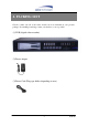
4. PACKING LIST Check to make sure all of the items shown below are included in your product package. If something is missing, contact your dealer as soon as possible.
5. INSTALLATION 5.
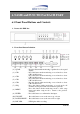
6. NAME and FUNCTION of EACH PART 6.1 Front Panel Buttons and Controls 1. Removable HDD Box 2. Front Panel Button Definition : Press this button under monitoring or quad mode to show quad display. CH 1 : Press this button under monitoring or record mode to show CH 1 in full-screen. CH 2 : Press this button under monitoring or record mode to show CH 2 in full-screen. CH 3 : Press this button under monitoring or record mode to show CH 3 in full-screen.
(13) (14) (15) (16) (17) (18) (19) (20) (21) PLAY LED MENU LED STOP LED REC STOP PAUSE REW PLAY F.F. : : : : : : : : : LED lights while playing playback. LED lights when entering setup menu. LED lights when entering stop mode. Press this button under monitoring mode to start recording. Press this button under playback to return to start monitoring. Press this button under playback to pause playback. Press this button under playback to start reverse scanning.
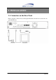
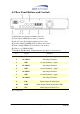
6.2 Rear Panel Buttons and Controls (1) RJ45: Internet connection terminal (optional). (2) Video Input [VIDEO IN]: Connect to cameras. (3) DC 12V (4A) [Power Input terminal]: power socket. (4) S-Video Output [S-VIDEO OUT]: Connect to the monitor. (5) Video Output [VIDEO OUT]: Connect to the monitor. (6) Video Loop [VIDEO LOOP]. (7) I/O Block [I/O BLOCK]: Terminal function description is shown below. No.
7. OPERATING PROCEDURE 7.1 Power On Each time after power on, DVR will auto-detect its peripherals (self-testing, warm-up, auto detects the hard disk and starts CF-card testing, and etc.) The system will detect the video input and judge whether the video system is NTSC or PAL. When video input is unable to be detected (VIDEO LOSS), the system will send out an alarm, press-on any button to stop the alarm (it will not affect the actual recording). 7.
7.3 Record Display Note:CH1: No block figure next to CH1 indicates that it is not recording. EACH: Record Type QUAD: Record Type (T): TIMER RECORD (A): ALARM RECORD (M): MIX RECORD (□): Currently under recording. VIDEO LOSS: Video input unable to be detected. CAMERA1: Name for CH 1. OFF: Channel is set to “OFF”.
7.4 Playback Display TIME SEARCH HARD DRIVE: MASTER 03/11/27 18:20:42 - 03/11/27 19:32:32 >01 TIME 2003/11/27 18:20:42 02 TIME 2003/11/27 16:43:56 03 TIME 2003/11/27 15:07:11 (<,>) MOVE (ENTER)CHANGE (PLAY)PLAY (MENU) EXIT (FF)SELECT EVENT OR TIME >01 TIME Total 7 >07 1. First press《STOP》button to stop record, then press《PLAY》button to enter search display. 2. Press《FF》button, then《PLAY》button to playback data from old to new.
7.5 Note! 1. “Auto Sequence” function operates only during recording or under live status (Dwell Time: 5 seconds). Sequencing will bypass a channel with video loss if programmed accordingly (Example: Video Loss occurs on CH3, sequencing order: CH1→CH2→CH4→QUAD). 2. To deactivate “Auto Sequence” function, press 1, 2, 3, 4, or QUAD. 3.
8. SYSTEM SETUP 8.1 Menu (1) (3) > SYSTEM SETUP CAMERA SETUP RECORD SETUP BUZZER SETUP EVENT LIST CF CARD SETTING HARD DRIVE SETUP (4) PRESS (< >), THEN (ENTER) PRESS (MENU) TO EXIT (2) (1) MAIN MENU: Item subject (First menu layer does not have a subject). (2) Menu Layer Indication: The device consists of four menu layers. ■ ■■ ■■■ ■■■■ :First Menu Layer (Main Menu) :Second Menu Layer :Third Menu Layer :Fourth Menu Layer (3) Menu Operation and Setup Press《←》or《→》button to move the cursor ( > ).
8.2 System Setup ■■ SYSTEM SETUP > TIME SET PASSWORD SET LOARD DEFAULT VERSION V1.0 PRESS(< >), THEN (ENTER) PRESS (MENU) TO EXIT 1. Cursor (>) position indicates the current function selected. 2. Press《←》and《→》button to move the cursor. 3. Press《ENTER》button to proceed. 4. Press《MENU》button to exit “System Setup”. 5. “System Setup"is situated on the second menu layer.
8.2.1 TIME SET ■■■ TIME 2005/01/11 17:23:06 ^ PRESS (< >), THEN (ENTER) PRESS (MENU) TO EXIT 1. Cursor (^) position indicates the current time and date selected. 2. Use《←》or《→》button to move the cursor. 3. Use《ENTER》button to setup time and date. 4. Use《MENU》button to exit “Time Setup”.
8.2.2 PASSWORD SET ■■■ PASSWORD SETUP > PASSWORD CHANGE MENU PASSWORD STOP REC PASSWORD OFF OFF PRESS (< >), THEN (ENTER) PRESS (MENU) TO EXIT 1. Cursor (>) position indicates the current function selected. 2. Use《←》and《→》button to move the cursor to the desired item . 3. Use《ENTER》button to make changes. 4. Use《MENU》button to exit “Password Setup”. 5.
8.2.2.1 PASSWORD CHANGE ■■■■ CURRENT PASSWORD :_ _ _ _ _ _ NEW PASSWORD :_ _ _ _ _ _ CONFIRM PASSWORD :_ _ _ _ _ _ PRESS (MENU) TO EXIT 1. Press《ENTER》button to show the display above. 2. Enter the current password (CURRENT PASSWORD). 3. Enter new password (NEW PASSWORD). 4. Confirm the new password (CONFIRM PASSWORD). 5. When password change is successful, the system will display “PASSWORD CHANGED”.
8.2.3 LOAD DEFAULT ■■■ PRESS (ENTER) TO RESET PRESS (MENU) TO EXIT 1. Press《ENTER》button to show the display above. 2. Press《ENTER》button the message《ALL SETTING DATA IS INITIALIZED》 will be displayed by flashing 3 times, and returns to default value. When reset procedure has been completed, the message“DVR RESET COMPLETED TURN OFF AND ON THE DVR"will be displayed, please restart the DVR. 3. Press《MENU》button to exit “Load Default Setup” selection.
8.3 Camera Setup ■■ CAMERA SETUP > CAMERA ENABLE CAMERA TITLE CAMERA SETTING CH1 TITLE CH2 TITLE CH3 TITLE CH4 TITLE 1234 ---CAMERA1 CAMERA2 CAMERA3 CAMERA4 PRESS (< >), THEN (ENTER) PRESS (MENU) TO EXIT 1. Cursor (>) position indicates the current function selected. 2. Press《←》and《→》button to move the cursor. 3. Press《ENTER》button to proceed. 4. Press《MENU》button to exit. 5. “Camera Setup” is situated on the second menu layer.
V CH1 TITLE CAMERA1 12345678 “V” indicates the position of the cursor. Press《←》and《→》button to move the cursor, and press《ENTER》button to change the title (maximum 8 characters). 8. All channel titles are setup the same way. Once the user formats the hard disk drive, the camera title returns to its default setting (CAMERA1/ CAMERA2/ CAMERA3/ CAMERA4). It is because this setup is stored in the hard disk drive.
8.3.1 CAMERA SETTING ■■■ CAMERA SEUP > CAMERA SELECT RECORD ENABLE MOTION DETECTION MOTION SENSITIVITY HUE CONTRAST BRIGHTNESS CH1 ON ON 03 08 08 08 PRESS (< >), THEN (ENTER) PRESS (MENU) TO EXIT 1. Cursor (>) position indicates the current function selected. 2. Press《←》and《→》button to move the cursor to the desired item. 3. Press《ENTER》button to make changes. 4. Press《MENU》button to exit “CAMERA SETUP” selection. 5. CAMERA SELECT: Press《ENTER》button to select the desired channel. 6.
8.4 Record Setup ■■ RECORD SETUP > RECORD TYPE VIDEO QUALITY TIME RECORD FRAMERATE MOTION RECORD FRAMERATE SENSOR RECORD FRAMERATE ALARM REC TIME RECORD MODE EACH NORMAL 04 15 15 10 PRESS (< >), THEN (ENTER) PRESS (MENU) TO EXIT 1. Cursor (>) position indicates the current function selected. 2. Use《←》and《→》button to move the cursor to the desired item. 3. Use《ENTER》button to make changes. 4. Use《MENU》button to exit “RECORD SETUP” selection. 5. “Record Setup” is situated on the second menu layer.
schedule record mode is setup to “M” (mix) or “A” (alarm). 10. SENSOR RECORD FRAMERATE: Press《ENTER》button to setup different recording speed, when a sensor device has been triggered (this setup is only active when the recording speed under schedule record mode is setup to “M”(Mix) or “A” (Alarm)). NTSC:30,15,10,7,5,4,3,2,1fps. PAL :25,12,8,6,4,3,2,1fps. 11.
1. Cursor (V) position indicates the current function selected. 2. Use《←》and《→》button to move the cursor to the desired item (time). 3. Use《ENTER》button to make changes. 4. Use《MENU》button to exit “SECHDULE RECORD MODE” selection. 5. T: Time, indicates continuous record. 6. M: TIME+MOTION+SENSOR. (1) When motion has been detected, it will be recorded by “Motion Record Speed”. (2) When sensor has been triggered, it will be recorded by “Sensor Record Speed”.
8.5 Buzzer Setup ■■ BUZZER SETUP > ALARM ALERT VIDEO LOSS ALERT HDD FULL ALERT BUZZER TIME RELAY OUT TIME SENSOR TYPE ON ON ON 05 05 PRESS (< >), THEN (ENTER) PRESS (MENU) TO EXIT 1. Cursor (>) position indicates the current selected position. 2. Press《←》and《→》button to move the cursor to the desired item (time). 3. Press《ENTER》button to proceed. 4. Press《MENU》button to exit “BUZZER SETUP” selection. 5. “BUZZER SETUP"is situated on the second menu layer.
8. HDD FULL ALERT: Press《ENTER》button to setup “ON” or “OFF”, whether to trigger the alarm when hard disk is full (this setup is only active when the system is under record status). 9. BUZZER TIME: Press《ENTER》button to setup the buzzer time to continuous (CONT), and press any button to release this setup. 10. RELAY OUT TIME: Press《ENTER》button to setup the relay out time to continuous (CONT), and press any button to release this setup. 8.5.
8.6 Event List EVENT LIST ■■ > TIME SEARCH EVENT SEARCH PRESS (< >), THEN (ENTER) PRESS (MENU) TO EXIT 1. Cursor (>) position indicates the current function selected. 2. Press《←》and《→》button to move the cursor to the desired item. 3. Press《ENTER》button to proceed. 4. Press《MENU》button to exit “EVENT LIST” selection. 5. “EVENT LIST"is situated on the second menu layer. Under this menu layer user may setup “TIME SERACH” or “EVENT SEARCH”.
8.6.1 TIME SEARCH TIME SEARCH ■■■ 05/01/13 19:27:16 BEGIN TIME: 05/01/13 19:27:16 END TIME: 05/01/15 15:00:06 PRESS (< >), THEN (ENTER) PRESS (MENU) TO EXIT 1. TIME SEARCH: Displays system recording time (begin and end). 2. Press《←》and《→》button to select the desired time and date. 3. Press《ENTER》button to setup playback starting time and date. 4. Press《MENU》button to exit “TIME SEARCH” selection. 5. Press《PLAY》button to play.
8.6.2 EVENT SEARCH EVENT SEARCH ■■■ BEGIN: 05/01/15 15:00:01 END: 05/01/15 15:00:06 > 01 ALARM 02 MIX 03 TIME 04 ALARM 2005/01/15 15:00:01 2005/01/15 14:00:01 2005/01/15 13:00:01 2005/01/15 12:00:01 PRESS (< >), THEN (ENTER) PRESS (MENU) TO EXIT 1. EVENT SEARCH: Displays all recording events, every page consists of 7 events, and maximum 63 stored events. 2. Press《←》and《→》button to select the desired event to playback. 3. Press《MENU》button to exit “EVENT SEARCH” selection. 4.
8.7 CF Card Setup ■■ CF CARD SETUP > COPY FORMAT/ERASE TOTAL CAPACITY 512MB REMAINING CAPACITY 100MB PRESS (< >), THEN (ENTER) PRESS (MENU) TO EXIT 1. Cursor (>) position indicates the current function selected. 2. Press《←》and《→》button to select the desired item. 3. Press《ENTER》button to proceed. 4. Press《MENU》button to exit “CF CARD SETUP” selection. 5.“CF CARD SETUP"is situated on the second menu layer. Under this menu layer user may setup to “COPY” or “FORMAT/ ERASE”. 6.
8.7.1 SELECT TIME ■■■ SELECT TIME > DAY 05/01/15 BEGIN TIME 15:00:01 END TIME 15:00:06 COPY PRESS (< >), THEN (ENTER) PRESS (MENU) TO EXIT 1. SELECT TIME: Displays the newest event date, begin and end time. 2. Press《←》and《→》button to select the desired item. 3. Press《ENTER》button to setup the desired date and time to proceed copy (COPY) function. 4. Press《MENU》button to exit “SELECT TIME” selection.
8.7.1.1 COPY ■■■■ (1) (2) (3) (4) (5) SELECT DATA:10MB ESTIMATED TIME:2 Minute START COPY CAPACITY IS NOT ENOUGH 10% COPIED (6) PRESS (ENTER) TO COPY (7) PRESS (MENU) TO EXIT (1)Data capacity. (2)Estimated time to complete data copy. (3)Request to confirm copy. (4)When the data capacity is greater than the remaining storage capacity, the message “CAPACITY IS NOT ENOUGH” will be displayed. (5)Data copy percentage completed. (6)Press《ENTER》button to start copy. (7)Press《MENU》button to exit “Copy Display”.
8.7.2 FORMAT/ ERASE ■■■ PASSWORD INPUT (6) :------ 1. When proceeding “FORMAT/ ERASE” function, the above display will be shown. 2. When password entered is correct, the screen will display the message “PASSWORD CORRECT”, “CF CARD FORMATED” (flashes 3 times), indicates CF Card format is successful. 3. When password entered is incorrect, the screen will display “PASSWORD INCORRECT” (flashes 3 times), and returns to “CF CARD SETUP” selection. ※ This password equals to hard disk format password.
8.8 Hard Drive Setup ■■ HARD DRIVE SETUP > DISK FULL OVERWRITE HDD SIZE 120103MB HDD USED 13321MB 11% HDD FORMAT PRESS (< >), THEN (ENTER) PRESS (MENU) TO EXIT 1. Cursor (>) position indicates the current function selected. 2. Press《←》and《→》button to select the desired item. 3. Press《ENTER》button to make changes or to proceed. 4. Press《MENU》button to exit “HARD DRIVE SETUP” selection. 5. “HARD DRIVE SETUP” is situated on the second menu layer.
8.8.1 HDD FORMAT: ■■■ PASSWORD INPUT (6) :------ 1. When proceeding “HDD FORMAT” function, the above display will be shown. 2. When password entered is correct, the screen will display the message “HDD FORMATTED” (flashes 3 times), indicates hard disk format is successful. 3. When password entered is incorrect, the screen will display “PASSWORD INCORRECT” (flashes 3 times), and returns to “HARD DRIVE SETUP” selection.
MEMO 37 DVR-4CF