DVR-IP4CF USER MANUAL Speco Technologies 200 New Highway Amityville, NY 11701 631-957-8700 www.specotech.
INDEX 1. SAFETY PRECAUTIONS ........................................................................... 3 2. INTRODUCTION........................................................................................ 4 2.1 P RODUCT I NTRODUCTION .......................................................................................4 2.2 A PPLICATION .........................................................................................................4 3. FEATURES ...............................................
9.3.8 R ESOLUTION S ETTING ....................................................................................... 48 9.3.9 A DVANCE S ETTINGS .......................................................................................... 48 9.4. C ONFIGURATION ................................................................................................. 48 9.4.1 S YSTEM S ETTING .............................................................................................. 48 9.4.2 U SER S ETTING ............
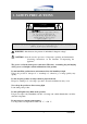
1. SAFETY PRECAUTIONS CAUTION RISK OF ELECTRIC SHOCK. DO NOT OPEN! C AUTION : TO REDUCE THE RISK OF ELECTRICAL SHOCK, DO NOT OPEN COVERS (OR BACK). NO USER SERVICEABLE PARTS INSIDE. REFER SERVICING TO QUALIFIED SERVICE PERSONNEL. It is advised to read the Safety Precaution Guide through carefully before operating the product, to prevent any possible danger. WARNING: Alert the user to the presence of un-insulated “dangerous voltage”.
2. INTRODUCTION 2.1 Product Introduction This world leading technology is perfect for office safety, personal home security, public environments, industrial surveillance, schools, and so on. It features quick and simple installation and is the best choice for your own ultimate protection. This state-of-the-art 4-channel digital recording system is equipped with an advanced embedded CPU operating system and powerful M-JPEG compression technology.
3. FEATURES z Auto video input detection Auto detects video input (NTSC/ PAL) and supports combined use of color and b/w cameras. z Supports high quality digital video recording Adopts M-JPEG compression technology (NTSC: 30fps/ PAL: 25fps). z Video Size Video Resolution • NTSC: 640x 224 • PAL: 640x 272 Monitoring Resolution • NTSC: 720x 480 • PAL: 720x 576 z Replaces a conventional VCR. Stores video on hard disks instead of VCR tapes. Large disk capacity, there is no need to replace the recording medium.
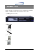
4. PACKING LIST Check to make sure all of the items shown below are included in your product package. If something is missing, contact your dealer as soon as possible.
5. INSTALLATION 5.
6. NAME and FUNCTION of EACH PART 6.1 Front Panel Buttons and Controls 1. Removable HDD Box 2. Front Panel Button Definition : Press this button under monitoring or quad mode to show quad display. CH 1 : Press this button under monitoring or record mode to show CH 1 in full-screen. CH 2 : Press this button under monitoring or record mode to show CH 2 in full-screen. CH 3 : Press this button under monitoring or record mode to show CH 3 in full-screen.
(13) (14) (15) (16) (17) (18) (19) (20) (21) PLAY LED MENU LED STOP LED REC STOP PAUSE REW PLAY F.F. : : : : : : : : : LED lights while playing playback. LED lights when entering setup menu. LED lights when entering stop mode. Press this button under monitoring mode to start recording. Press this button under playback to return to start monitoring. Press this button under playback to pause playback. Press this button under playback to start reverse scanning.
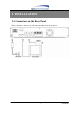
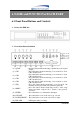
6.2 Rear Panel Buttons and Controls (1) RJ45: Internet connection terminal (2) Video Input [VIDEO IN]: Connect to cameras. (3) DC 12V (4A) [Power Input terminal]: Power socket. (4) S-Video Output [S-VIDEO OUT]: Connect to the monitor. (5) Video Output [VIDEO OUT]: Connect to the monitor. (6) Video Loop [VIDEO LOOP THROUGH]. (7) I/O Block [I/O BLOCK]: Terminal function description is shown below. No.
7. OPERATING PROCEDURE 7.1 Power On When powered on, the DVR will auto-detect its peripherals (self-testing, warm-up, auto detects the hard disk and starts CF-card testing, and etc.) The system will detect the video input and judge whether the video system is NTSC or PAL. When video input is unable to be detected (VIDEO LOSS), the system will send out an alarm, press any button to stop the alarm (it will not affect the actual recording).
7.3 Record Display Note:CH1: No block figure next to CH1 indicates that it is not recording. EACH: Record Type QUAD: Record Type (T): TIMER RECORD (A): ALARM RECORD (M): MIX RECORD (□): Currently under recording. VIDEO LOSS: Video input unable to be detected. CAMERA1: Name for CH 1. OFF: Channel is set to “OFF”.
7.4 Playback Display TIME SEARCH HARD DRIVE: MASTER 03/11/27 18:20:42 - 03/11/27 19:32:32 >01 TIME 2003/11/27 18:20:42 02 TIME 2003/11/27 16:43:56 03 TIME 2003/11/27 15:07:11 (<,>) MOVE (ENTER)CHANGE (PLAY)PLAY (MENU) EXIT (FF)SELECT EVENT OR TIME >01 TIME Total 7 >07 1. Press《STOP》button to stop recording, then press《PLAY》button to enter the search . 2. Press《FF》button, then《PLAY》button to playback data from old to new.
7.5 Note! 1. “Auto Sequence” function operates only during recording and under live status (Dwell Time: 5 seconds). Sequencing will bypass a channel with video loss if programmed accordingly (Example: Video Loss occurs on CH3, sequencing order: CH1→CH2→CH4→QUAD). 2. To deactivate “Auto Sequence” function, press 1, 2, 3, 4, or QUAD. 3.
8. SYSTEM SETUP 8.1 Menu (1) (3) > SYSTEM SETUP CAMERA SETUP RECORD SETUP BUZZER SETUP EVENT LIST CF CARD SETTING HARD DRIVE SETUP (4) PRESS (< >), THEN (ENTER) PRESS (MENU) TO EXIT (2) (1) MAIN MENU: Item subject (First menu layer does not have a subject). (2) Menu Layer Indication: The device consists of four menu layers. ■ ■■ ■■■ ■■■■ :First Menu Layer (Main Menu) :Second Menu Layer :Third Menu Layer :Fourth Menu Layer (3) Menu Operation and Setup Press《←》or《→》button to move the cursor ( > ).
8.2 System Setup ■■ SYSTEM SETUP > TIME SET PASSWORD SET LOARD DEFAULT VERSION V1.0 PRESS(< >), THEN (ENTER) PRESS (MENU) TO EXIT 1. Cursor (>) position indicates the current function selected. 2. Press《←》and《→》button to move the cursor. 3. Press《ENTER》button to proceed. 4. Press《MENU》button to exit “System Setup”. 5. “System Setup"is situated on the second menu layer.
8.2.1 TIME SET ■■■ TIME 2005/01/11 17:23:06 ^ PRESS (< >), THEN (ENTER) PRESS (MENU) TO EXIT 1. Cursor (^) position indicates the current time and date selected. 2. Use《←》or《→》button to move the cursor. 3. Use《ENTER》button to setup time and date. 4. Use《MENU》button to exit “Time Setup”.
8.2.2 PASSWORD SET ■■■ PASSWORD SETUP > PASSWORD CHANGE MENU PASSWORD STOP REC PASSWORD OFF OFF PRESS (< >), THEN (ENTER) PRESS (MENU) TO EXIT 1. Cursor (>) position indicates the current function selected. 2. Use《←》and《→》button to move the cursor to the desired item . 3. Use《ENTER》button to make changes. 4. Use《MENU》button to exit “Password Setup”. 5.
8.2.2.1 PASSWORD CHANGE ■■■■ CURRENT PASSWORD :_ _ _ _ _ _ NEW PASSWORD :_ _ _ _ _ _ CONFIRM PASSWORD :_ _ _ _ _ _ PRESS (MENU) TO EXIT 1. Press《ENTER》button to show the display above. 2. Enter the current password (CURRENT PASSWORD). 3. Enter new password (NEW PASSWORD). 4. Confirm the new password (CONFIRM PASSWORD). 5. When password change is successful, the system will display “PASSWORD CHANGED”.
8.2.3 LOAD DEFAULT ■■■ PRESS (ENTER) TO RESET PRESS (MENU) TO EXIT 1. Press《ENTER》button to show the display above. 2. Press《ENTER》button the message《ALL SETTING DATA IS INITIALIZED》 will be displayed by flashing 3 times, and returns to default value. When reset procedure has been completed, the message“DVR RESET COMPLETED TURN OFF AND ON THE DVR"will be displayed, please restart the DVR. 3. Press《MENU》button to exit “Load Default Setup” selection.
8.3 Camera Setup ■■ CAMERA SETUP > CAMERA ENABLE CAMERA TITLE CAMERA SETTING CH1 TITLE CH2 TITLE CH3 TITLE CH4 TITLE 1234 ---CAMERA1 CAMERA2 CAMERA3 CAMERA4 PRESS (< >), THEN (ENTER) PRESS (MENU) TO EXIT 1. Cursor (>) position indicates the current function selected. 2. Press《←》and《→》button to move the cursor. 3. Press《ENTER》button to proceed. 4. Press《MENU》button to exit. 5. “Camera Setup” is situated on the second menu layer.
below: V CH1 TITLE CAMERA1 12345678 “V” indicates the position of the cursor. Press《←》and《→》button to move the cursor, and press《ENTER》button to change the title (maximum 8 characters). 8. All channel titles are setup the same way. Once the user formats the hard disk drive, the camera title returns to its default setting (CAMERA1/ CAMERA2/ CAMERA3/ CAMERA4). It is because this setup is stored in the hard disk drive.
8.3.1 CAMERA SETTING ■■■ CAMERA SEUP > CAMERA SELECT RECORD ENABLE MOTION DETECTION MOTION SENSITIVITY HUE CONTRAST BRIGHTNESS CH1 ON ON 03 08 08 08 PRESS (< >), THEN (ENTER) PRESS (MENU) TO EXIT 1. Cursor (>) position indicates the current function selected. 2. Press《←》and《→》button to move the cursor to the desired item. 3. Press《ENTER》button to make changes. 4. Press《MENU》button to exit “CAMERA SETUP” selection. 5. CAMERA SELECT: Press《ENTER》button to select the desired channel. 6.
8.4 Record Setup ■■ RECORD SETUP > RECORD TYPE VIDEO QUALITY TIME RECORD FRAMERATE MOTION RECORD FRAMERATE SENSOR RECORD FRAMERATE ALARM REC TIME RECORD MODE EACH NORMAL 04 15 15 10 PRESS (< >), THEN (ENTER) PRESS (MENU) TO EXIT 1. Cursor (>) position indicates the current function selected. 2. Use《←》and《→》button to move the cursor to the desired item. 3. Use《ENTER》button to make changes. 4. Use《MENU》button to exit “RECORD SETUP” selection. 5. “Record Setup” is situated on the second menu layer.
different recording speeds per channel, suitable when the recording speed under schedule record mode is setup to “M” (mix) or “A” (alarm). 10. SENSOR RECORD FRAMERATE: Press《ENTER》button to setup different recording speed, when a sensor device has been triggered (this setup is only active when the recording speed under schedule record mode is setup to “M”(Mix) or “A” (Alarm)). NTSC:30,15,10,7,5,4,3,2,1fps. PAL :25,12,8,6,4,3,2,1fps. 11.
1. Cursor (V) position indicates the current function selected. 2. Use《←》and《→》button to move the cursor to the desired item (time). 3. Use《ENTER》button to make changes. 4. Use《MENU》button to exit “SECHDULE RECORD MODE” selection. 5. T: Time, indicates continuous record. 6. M: TIME+MOTION+SENSOR. (1) When motion has been detected, it will be recorded by “Motion Record Speed”. (2) When sensor has been triggered, it will be recorded by “Sensor Record Speed”.
8.5 Buzzer Setup ■■ BUZZER SETUP > ALARM ALERT VIDEO LOSS ALERT HDD FULL ALERT BUZZER TIME RELAY OUT TIME SENSOR TYPE ON ON ON 05 05 PRESS (< >), THEN (ENTER) PRESS (MENU) TO EXIT 1. Cursor (>) position indicates the current selected position. 2. Press《←》and《→》button to move the cursor to the desired item (time). 3. Press《ENTER》button to proceed. 4. Press《MENU》button to exit “BUZZER SETUP” selection. 5. “BUZZER SETUP"is situated on the second menu layer.
to trigger the alarm when hard disk is full (this setup is only active when the system is under record status). 9. BUZZER TIME: Press《ENTER》button to setup the buzzer time to continuous (CONT), and press any button to release this setup. 10. RELAY OUT TIME: Press《ENTER》button to setup the relay out time to continuous (CONT), and press any button to release this setup. 8.5.
8.6 Event List EVENT LIST ■■ > TIME SEARCH EVENT SEARCH PRESS (< >), THEN (ENTER) PRESS (MENU) TO EXIT 1. Cursor (>) position indicates the current function selected. 2. Press《←》and《→》button to move the cursor to the desired item. 3. Press《ENTER》button to proceed. 4. Press《MENU》button to exit “EVENT LIST” selection. 5. “EVENT LIST"is situated on the second menu layer. Under this menu layer user may setup “TIME SERACH” or “EVENT SEARCH”.
8.6.1 TIME SEARCH TIME SEARCH ■■■ 05/01/13 19:27:16 BEGIN TIME: 05/01/13 19:27:16 END TIME: 05/01/15 15:00:06 PRESS (< >), THEN (ENTER) PRESS (MENU) TO EXIT 1. TIME SEARCH: Displays system recording time (begin and end). 2. Press《←》and《→》button to select the desired time and date. 3. Press《ENTER》button to setup playback starting time and date. 4. Press《MENU》button to exit “TIME SEARCH” selection. 5. Press《PLAY》button to play.
8.6.2 EVENT SEARCH EVENT SEARCH ■■■ BEGIN: 05/01/15 15:00:01 END: 05/01/15 15:00:06 > 01 ALARM 02 MIX 03 TIME 04 ALARM 2005/01/15 15:00:01 2005/01/15 14:00:01 2005/01/15 13:00:01 2005/01/15 12:00:01 PRESS (< >), THEN (ENTER) PRESS (MENU) TO EXIT 1. EVENT SEARCH: Displays all recording events, every page consists of 7 events, and maximum 63 stored events. 2. Press《←》and《→》button to select the desired event to playback. 3. Press《MENU》button to exit “EVENT SEARCH” selection. 4.
8.7 CF Card Setup ■■ CF CARD SETUP > COPY FORMAT/ERASE TOTAL CAPACITY 512MB REMAINING CAPACITY 100MB PRESS (< >), THEN (ENTER) PRESS (MENU) TO EXIT 1. Cursor (>) position indicates the current function selected. 2. Press《←》and《→》button to select the desired item. 3. Press《ENTER》button to proceed. 4. Press《MENU》button to exit “CF CARD SETUP” selection. 5.“CF CARD SETUP"is situated on the second menu layer. Under this menu layer user may setup to “COPY” or “FORMAT/ ERASE”. 6.
8.7.1 SELECT TIME ■■■ SELECT TIME > DAY 05/01/15 BEGIN TIME 15:00:01 END TIME 15:00:06 COPY PRESS (< >), THEN (ENTER) PRESS (MENU) TO EXIT 1. SELECT TIME: Displays the newest event date, begin and end time. 2. Press《←》and《→》button to select the desired item. 3. Press《ENTER》button to setup the desired date and time to proceed copy (COPY) function. 4. Press《MENU》button to exit “SELECT TIME” selection.
8.7.1.1 COPY ■■■■ (1) (2) (3) (4) (5) SELECT DATA:10MB ESTIMATED TIME:2 Minute START COPY CAPACITY IS NOT ENOUGH 10% COPIED (6) PRESS (ENTER) TO COPY (7) PRESS (MENU) TO EXIT (1)Data capacity. (2)Estimated time to complete data copy. (3)Request to confirm copy. (4)When the data capacity is greater than the remaining storage capacity, the message “CAPACITY IS NOT ENOUGH” will be displayed. (5)Data copy percentage completed. (6)Press《ENTER》button to start copy. (7)Press《MENU》button to exit “Copy Display”.
8.7.2 FORMAT/ ERASE ■■■ PASSWORD INPUT (6) :------ 1. When proceeding “FORMAT/ ERASE” function, the above display will be shown. 2. When password entered is correct, the screen will display the message “PASSWORD CORRECT”, “CF CARD FORMATED” (flashes 3 times), indicates CF Card format is successful. 3. When password entered is incorrect, the screen will display “PASSWORD INCORRECT” (flashes 3 times), and returns to “CF CARD SETUP” selection. ※ This password equals to hard disk format password.
8.8 Hard Drive Setup ■■ HARD DRIVE SETUP > DISK FULL OVERWRITE HDD SIZE 120103MB HDD USED 13321MB 11% HDD FORMAT PRESS (< >), THEN (ENTER) PRESS (MENU) TO EXIT 1. Cursor (>) position indicates the current function selected. 2. Press《←》and《→》button to select the desired item. 3. Press《ENTER》button to make changes or to proceed. 4. Press《MENU》button to exit “HARD DRIVE SETUP” selection. 5. “HARD DRIVE SETUP” is situated on the second menu layer.
8.8.1 HDD FORMAT: ■■■ PASSWORD INPUT (6) :------ 1. When proceeding “HDD FORMAT” function, the above display will be shown. 2. When password entered is correct, the screen will display the message “HDD FORMATTED” (flashes 3 times), indicates hard disk format is successful. 3. When password entered is incorrect, the screen will display “PASSWORD INCORRECT” (flashes 3 times), and returns to “HARD DRIVE SETUP” selection.
9. NETWORK OPERATION 9.1 Network DVR Setup Before installing the Network DVR, you need to first setup an IP Address, connect it to the ADSL Modem or LAN Hub, and use IPEdit.exe to test the DVR. Note: Before using PPPoE and DDNS connection method, one must first setup an IP Address (using IPEDIT.exe). 9.1.1 Online with DHCP Server Use IPEDIT.exe to find the installed Network DVR. Select this Network DVR in the Camera List Window. The default configuration will be shown on the right window.
9.1.2 Online without DHCP Server 1. Use IPEdit.exe to find the installed Network DVR. 2. The Internet DVR without IP allocated by DHCP will have a default IP Address of 169.254.1.13. 3. Select this Internet DVR on Camera List Window. 4. The default configuration will be shown on the right window. 5. Under DOS mode enter “IPCONFIG” to access Gateway, IP, and Netmask setting values. Online without DHCP Server After the “Submit” button is clicked, the IP information of this Network DVR will be updated. 9.
9.2.1 Online using Intranet or Fixed IP Setup similar to “9.1 Network DVR Setup” . 9.2.2 Online using ADSL (PPPoE) Router Setup similar to “9.4.3.3 Connect to ADSL by PPPoE mode”. 9.2.3 Online using DDNS Server The DDNS service provides the dynamic IP to users to gain access to resources connected to the Internet via a cable or DSL connection. Once you’ve decided to apply this function, please register your domain name at http://www.dyndns.org (this website supports register free service).
9.2.4.1 Install ActiveX Before entering remote connection, please install ActiveX and check your browser setup by following the procedures below: a. Open Internet Explorer under “Tools” and select “Internet Options”. Tools Æ Internet Options b. Select “Security”, and then press “Custom Level”.
Start-up ActiveX Control 42 DVR-IP4CF
The graphic below will be shown when first time installing ActiveX Mode. Please, select “Yes” to accept installation. Download ActiveX Control Live view will be displayed when installation is successful.
Live display under ActiveX mode 9.3 Main Display 1 ○ 3 ○ 4 ○ 2 ○ Remote control DVR - Main Menu 1 Live Display ○ 2 DVR Control Button ○ 3 Video Setup ○ 4 Configuration: Enter detail setup ○ Recording: Displays recording setup menu (for video recording). Snapshot: Pop-up window displays live images, right mouse click to save. Note! To view complete interface, PC resolution must be adjusted to 1024*768. 9.3.
9.3.2 View Two types of display method: a. Resizable: Adjustable image size. b.Actual size: The actual image size. 9.3.3 Rotate Four types of rotate settings: a. Rotate 0: Default state b.Rotate 180: Rotate the image by 180 degrees. c. Flip horizontal: Image flips horizontally d.
9.3.4 Image Recording Image Recording Setup Display: Save as JPEG: Save as picture file Save as AVI: Save as AVI animation file Save as JPEG: No Limit: Unrestricted image storage (continuous). Number: Image storage according to “number”. Save interval: Image storage according to “1/10 second” (e.g.: Enter “10”, then 1 frame is stored per second. Enter “50”, then 1 frame is stored in 5 seconds). Size: Image storage according to “size”. Time: Image storage according to “time”.
9.3.5 Save Current Picture Select to save live images. 9.3.6 DVR Control Setup Supports DVR remote control function (Please refer to 6-1 Front Panel Buttons and Controls, on page 8). 9.3.7 Quality Setting Network DVR provides 5 image quality settings. The user can select the quality setting from the “Quality” list box.
9.3.8 Resolution Setting Network DVR provides six resolution settings. The user can select the quality setting from the “Resolution” list box. z 176x144 z 160x120 z 320x240 z 352x288 z 640x480 z 704x576 Note! The device supports auto video system detection (NTSC/ PAL). 9.3.9 Advance Settings Network DVR provides the advanced settings for the following: z z z z Brightness Contrast Saturation Hue 9.4.
z z z Reboot DVR: The system need 20 seconds to reboot the DVR (Rebooting does not effect the recording function). FirmWare update (Please refer to 6.7). ReStore Factory Default 9.4.2 User Setting z z z z User Authorization Setting Add User or Change Password Delete User Account Current Users User Setting Display 9.4.2.
9.4.2.2 New user/ Change Password Enter a new user name and password information to create a new user account, or enter an existing user account, then set a new password to replace the old password, and select “OK” to create the account or change password. After selecting “OK” button, the “Current User List” would display the newly created user account. 9.4.2.3 Delete User Enter the user account that you wish to delete, click “OK” to delete the account.
9.4.3.2 DHCP The “DHCP” is automatically set as the default network setting of the Network DVR. When a Network DVR is connected into the LAN, it will issue DHCP packets to request an IP address that is dynamically assigned by the DHCP server. If it is unable to get a DHCP address on a limited tries, the Network DVR will assign a default IP address such as “169.254.1.13”. 9.4.3.3 Connect to ADSL by PPPoE mode To setup follow the steps below: 1. After setup, rebooting enables automatic connection to ADSL. 2.
1. Power off Network DVR. 2. Connect Network DVR directly to the ADSL modem (using RJ-45 Ethernet port). 3. Power-up Network DVR. 4. Network DVR start dialing. 5. Once connected, mail the IP address information to the preset e-mail address. 6. After 10 times of connection failure, it aborts the operation and the user can reconnect it by LAN to find the cause.
To setup follow the steps below: 1. Register at DDNS Server: http://www.dyndns.org. 2. Apply domain name. 3. Click the “Enable” button. Enter “UserName” and “Password” with “DomainName”. DDNS Setting After registering the domain name, please enter the information supplied by the administrator to the Network DVR DDNS Account Setting. Select “Enable” button to start-up DDNS server, and press “Submit” button to save the setting.
9.4.5 Firmware Update When new firmware (bin file) is supplied, you may update the new version firmware (bin file) to your PC by following the procedures below: Select the Firmware to be Updated Uploading the Selected Firmware Press “Upload” button to display the message below, and follow the instruction to make the necessary setup.
Press “here” button (1) to update Firmware. Press “here” button (2) to delete the file. The message below displays the writing progress of the firmware update. When Firmware update is completed, it will show 100%, and a message “Click here to reboot DVR browser” will be displayed, requesting to restart the Network DVR. Firmware Update Display Firmware Update Completed, prompt to restart the device.
10. CF Card/ HDD Player Software Description PC Player Software System Requirement ※ OS (Operating System) Windows 2000/ XP or later. ※ Use your PC to install DirectX (version DirectX 7.0 or above). ※ Using remote control software, please setup the resolution to 1024x768 or above. Hardware Requirement ※CPU 1.0 GHz or higher. ※RAM 256 Mbyte or higher. 1. Installation A. Hardware Installation Make sure that HDD or CF card is connected through IDE or USB interface to the PC. B. Software Installation 1.
3. Software Playback Interface Description A. User Interface Play System System Status Figure 1 When the system detects stored materials (HDD or CF card), the above graphic (Figure 1) will be shown. User may operate the function buttons to make necessary playback adjustment or store recordings onto the PC.
:Recording Material Stored :Step Back One Frame :Pause Playback :Step Forward One Frame :Quad split screen display :CH2 Full Screen Display :CH4 Full Screen Display :Click this button to capture images as BMP file, graphic shown by “Figure 2” will be shown and PC Player Software auto creates a storage content “Capture MYS”. :When recording videos onto the PC, first click the “Pause” button, then “Now Recording” button on the graphic shown by “Figure 3”.
Figure 2 Figure 3 59 DVR-IP4CF
Figure 4 Figure 5 60 DVR-IP4CF
B.
11. TROUBLESHOOTING Question Answer Why can’t the device read the hard Please reinstall the hard disk, make sure that it disk? is properly connected, and reboot the device. Why can’t the device read the CF Please reinsert the CF card, make sure that it card? is properly connected and reboot the device. Suggested HDD Brand Maxtor, Seagate, and Hitachi. Suggested CF card Brand Apacer, Sandisk, Transcend, Hagiware, A-DATA and Silicon.
12. SPECIFICATIONS Format Video Display Recording HDD NTSC/EIA or PAL/CCIR Compression Modified M-JPEG Input 4CH, BNC Output 1 x BNC, 1 x S-Video Resolution 720 x 480 (NTSC), 720 x 576 (PAL) Frame Rate Max. 120/100 fps (NTSC/PAL) Division Single, Quad, Sequence Resolution Max. 640 x 244 (NTSC), 640 x 272 (PAL) Frame Rate Max. 30/25 fps (NTSC/PAL) Quality High / Normal / Low Mode Manual / Schedule / Alarm / Motion Detection Format 1 x 3.5” IDE HDD (Max.
MEMO 64 DVR-IP4CF