USER MANUAL 4-CHANNEL TRIPLEX NETWORK DVR DVR-T4IP * Default system password: 111111 (for RAMS, Record stop, Menu setup, System off, Auto key lock) * Default ID: admin (for RAMS) Speco Technologies, 200 New Highway Amityville, N.Y. 11701 Toll Free : 1-800-645-5516 In Metro NY : 631-957-8700 Fax:631-957-9142 or 631-957-3880 Web:www.specotech.
To prevent fire or shock hazard, do not expose the unit to rain WARNING or moisture. The symbol is intended to alert the user to the presence of important operating and maintenance (servicing) instructions in the literature accompanying the unit. The symbol is intended to alert the user to the presence of uninsulated "dangerous voltage" within the product's enclosure that may be of sufficient magnitude to constitute a risk of electric shock to persons.
Safety Instructions 1) Read these instructions. 2) Keep these instructions. 3) Heed all warnings. 4) Follow all instructions. 5) Do not use this apparatus near water. 6) Clean only with dry cloth. 7) Do not block any ventilation openings. Install in accordance with the manufacturer’s instructions. 8) Do not install near any heat sources such as radiators, heat registers, stoves, or other apparatus (including amplifiers) that produce heat.
Table of contents 1. SYSTEM OVERVIEWS ..........................................................13 1.1 PACKING LIST ....................................................................................................................... 13 1.1.1 Components......................................................................................................................... 13 1.1.2 Options ...........................................................................................................
2.6.1 Press the Play button ........................................................................................................... 25 2.6.2 Audio files........................................................................................................................... 25 2.7 SEARCH ................................................................................................................................ 25 2.7.1 Search mode ..........................................................
3.2.2.3 Channel number .................................................................................................................................. 34 3.2.2.4 Quality ................................................................................................................................................ 34 3.2.2.5 Frame rate ........................................................................................................................................... 34 3.2.2.
3.3.8.3 SMTP Server IP address ..................................................................................................................... 47 3.3.8.4 Authentication..................................................................................................................................... 47 3.3.9 3.4 Event Log ............................................................................................................................ 48 PLAYBACK SETUP ..............................
3.7.5 Language ............................................................................................................................. 62 3.7.6 System Log.......................................................................................................................... 62 3.7.7 HDD Setup .......................................................................................................................... 62 3.7.7.1 The number of HDD ................................................
3.11 PLAYBACK........................................................................................................................ 73 3.11.1 3.11.1.1 Method of playback ............................................................................................................................ 73 3.11.1.2 Screen of played back. ........................................................................................................................ 73 3.11.1.3 Control during play back.............
4.3.21 4.4 Close program ..................................................................................................................... 93 UNIPLAYER .......................................................................................................................... 93 4.4.1 Screen and button ................................................................................................................ 93 4.4.2 Search.....................................................................
5.1.1 Installing single hard disk drive .........................................................................................113 5.1.2 Installing two hard disk drives. ..........................................................................................114 5.1.3 Installing CD-RW drive......................................................................................................115 5.2 TERMINAL INFORMATION ............................................................................
All rights reserved. No part of this publication may be reproduced or transmitted in any form or any means, electronic or mechanical, including photocopy, recording, or any information storage and retrieval system, without prior permission.
1. SYSTEM OVERVIEWS 1.1 Packing list The following items are included with the DVR-T4IP . Please be certain that all items are included as soon as you open the box: 1.1.1 Components DVR-T4IP (Main Assembly) Power cable Rack mount brackets DSUB-15 connector for PTZ /AUX / ALARM Quick Manual Software CD (RAMS, UniPlayer, MultiViewer, QuickInstaller and Operation Manual) Removable external Hard disk drive rack key & screw 1.1.
1.2 Features & specifications 1.2.
1.2.
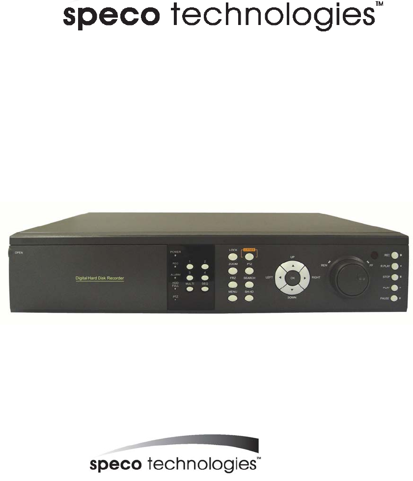
1.3 Name, function & connections 1.3.1 Front view 1 2 3 4 5 6 7 Description: 1. Removable HDD Rack or CD-RW Rack Removable Hard Disk Drive or CD RW Drive 2. LED indicator POWER: Power Off status is indicated by a Red light and ON status is indicated by a Green light. REC: Green light (Recording) ALARM: Green light (Alarm triggered) HDD FULL: Green light (No more disk space for recording) PTZ: Pan, Tilt, Zoom, Focus status is indicated by Green 3.
ZOOM: Zoom In/Out on the images during Live Viewing. FRZ : Freeze. - Press button once to freeze the frame at live mode. Press again to return. - To take a still image capture at playback mode. -Exchange of video input type : Press power button with FRZ button from NTSC to Pal or PAL to NTSC. MISC/SH: Miscellaneous functions or Shuttle Hold. - MISC: To substitute for the five buttons that are placed on the remote control but on the keypad (NET, OSD, Audio Mute, HDD, LOG).
8. Recording/Playback buttons RECORD: Press once to begin recording all active channels. Press again to end recording. R-PLAY: Reverse Playback. Press to begin reverse playback. Under PTZ control menu, used to decrease the speed of Pan, Tilt, Zoom, Focus. STOP: Stop playback. PLAY: Access to playback. - Playback button will activate assigned starting position and Channel at playback setup of menu. - At pause mode, it will release pause mode.
6. VIDEO OUT Terminals for composite video and s-video to connect with monitor 7. CAMERA IN: Video input (to connect with camera output) OUT: Video output (Loop-through output for video input) 8. FAN Heat protection fan to reduce heat in the unit 9.
1.3.
1.4 INSTALLATION 1.4.1 Installation and connection AUX OUT Camera 1 PTZ Reciever RS-485 Monitor Sensor 1 Network AUX IN Sensor 2 Mic Speak Camera 2 Camera 3 Sensor 3 Alarm USB Sensor 4 Camera 4 1.4.1.1 Camera The unit comes with 4 video IN and 4 video OUT for up to four camera connection. Connect to 'IN' terminal for video input and to 'OUT' for loopthrough output.
1.4.1.3 Audio : support or not support Use IN for a Line input and OUT for speaker output. 1.4.1.4 RS-232 Use this connector to connect RS-232 cable to the serial port on your PC to control the DVR or to perform Quick Installation. 1.4.1.5 PTZ/AUX/ALARM 1.4.1.5.1 RS-485+, RS-485DVR-T4IP uses RS-485 protocol to control PTZ Receiver, Speed Dome, and Auto-focus camera. Be sure to match the polarity. 1.4.1.5.
1.4.1.5.4 Sensor 1~4 Users can connect up to four N.O./N.C. type sensors and configure them within Main Menu, Sensor Setting. 1.4.1.6 Network Connect RJ-45 Ethernet cable. 1.4.1.7 USB flash memory Perform backup of recorded video files from DVR system to USB flash memory manually.
2. Basic operation procedures 2.1 Power On/Off 2.1.1 Power on Using either the keypad or the remote control, press the “Power” button. (Note: In case of power outage or rare instance of system failure, the DVR will reboot automatically) The Power LED light will turn from red to green when it has turned on properly. In a standby mode, the LED is red. 2.1.2 Power OFF In order to shutdown the system, you must type in the password. The default password for shutdown is “111111”. 2.
2.5.1 Recording types There are two types of recording: MUX or QUAD type. For resolution, select either D1 (720*480 (NTSC), 720*576 (PAL)) or CIF (360*240 (NTSC), 360*288 (PAL)). Audio channel is synchronized with the selected video signal. Select Video input quality, Frame rate, and recording mode. 2.5.2 Recording modes Recording mode are made up of MANUAL, CONTINUOUS, MOTION, SENSOR, MOTION+SENSOR, and SCHEDULE mode.
2.8 Backup The DVR-T4IP has various types of backup methods: 2.8.1 Removable HDD If there are two hard disk drives equipped in the DVR, the removable HDD will be used as a backup drive. MANUAL BACKUP, AUTO BACKUP will be selectable for backup. MANUAL BACKUP: Execute backup during user’s preferable setting. AUTO BACKUP: 2.8.2 Execute backup accordingly whenever new recording file was made.
2.9 Client Program 2.9.1 RAMS (Remote Access & Monitoring System) Remotely access, monitor, and operate the DVR for real-time live viewing, playback, backup, on-the-fly recording, and control over the LAN/WAN Upgrade the S/W(Kernel, Ramdisk) of DVR Install the RAMS program as referred to in section 4.2 of Operation Manual. Execute RAMS program and register selected DVR’s IP address & Port number from the DVR list. After selecting the target DVR, enter “admin” for ID and “111111” for default password.
3. Main Setup screen Figure 3-1 Main Setup screen 3.
3.1.1 Channel number. A user can select targeted camera from CH #1 ~ CH # 4. After setting, this, live viewing picture will be changed to selected channel automatically. 3.1.2 Camera Name Edit Figure 3-3 Camera name edit screen User can edit camera name indicated button part of each channel. as explained paragraph 2.1.1.
3.1.4 PTZ setup Figure 3-4 PTZ setup screen It sets PTZ protocol of targeted channel in the Camera Setup. (Please refer to paragraph 3.1.1 for channel selection) 3.1.4.1 Model Number Select the PTZ model or choose “NONE”. 3.1.4.2 PTZ ID Set the PTZ ID: 0 ~ 255 The PTZ ID must match the ID number that has been set by the PTZ Controller. Please verify the ID on the Controller first before setting the PTZ ID. 3.1.4.
3.1.4.4 RS-485 Setting Choose from the following to set PTZ RS-485 baud rate: 2400, 4800, 9600, 19200, 38400, 57600, 115200 bps. 3.1.4.5 TEST Users can test the PTZ control after setting the parameters. After clicking the TEST button, PTZ control will be available and tested by up/down key. Pan/tilt and Zoom/Focus mode will be controlled after entering OK key button.
Preset numbers are selected by Left/Right buttons and the Pan/Tilt drive moves to the preset position after pressing OK button. - Light : To turn on/off the camera lighting selected by Left/Right and OK buttons. - Camera : To turn on/off the camera itself selected by Left/Right and OK buttons. - Aux : To turn on/off the AUX (two) connected to the camera. On/off are selected by Left/Right and OK buttons. - Auto Pan : To automatically pan the camera.
3.2 Record Setup menu 3.2.1 Record Type Users can select either Quad mode or MUX mode for recording type. MUX Recording records full size recording sequentially from each channel. Quad recording records 4 channel video signal as one same picture and each channel has quad sliced size. Under MUX Recording mode, resolution will be applicable to all channel. Picture quality, recording time, and recording mode can be selected channel by channel.
3.2.2.2 Audio Sync As audio input port is one channel available, user should synchronize audio signal with targeted video signal. With synchronized channel will record audio as well as video. But others will only record video input signal only. 3.2.2.3 Channel number Under MUX recording mode, quality, frame rate will be selected per channel. So users can choose targeted channel. 3.2.2.
alarm recording will be controlled at Post alarm recording time on Event Setup Menu. (Refer to paragraph 3.3.4) • Sensor: Start to record under sensor input. As same as motion mode, it starts pre alarm recording around 2 or 3 second and maintain it until no of sensor input. Post-alarm recording will be controlled at Post alarm recording time on Event Setup Menu. (Refer to paragraph 3.3.2) • Motion + Sensor: Start to recording under motion detection or Sensor occurrence.
3.2.3.3 Audio ON/OFF User can set audio on/off function. If used Audio On mode, audio signal will be recorded simultaneously with video and used audio off mode, audio signal not be recorded. 3.2.3.4 Frame rate 3.2.3.4.1 NTSC User can set the recording Frame rate at Quad Recording, none (Non recording), 1, 2, 3, 5, 7, 10, 15, 30 fps will be selectable. This setting is applicable to all channels as equal forms. 3.2.3.4.
User can select to set recording schedule targeted date, time based week & 24Hours. Move the cursor to the desired position of time by pressing up/down key and set the recording mode at the desired position of time by pressing the OK button with referring to the Help Message per Record Mode on the right position. After the setup, store the set schedule and exit to the top menu by pressing the Menu button. 3.
3.3.1 Motion Detection Setting Figure 3-11 Motion Detecting Setup screen Sets up the motion detecting area and sensitivity. It sets up all 4 channels when it is set on the Quad recording. 3.3.1.1 Channel Sets up the motion detecting area and sensitivity for each channel. It sets up all 4 channels when it is set on the Quad recording. Under Quad recording mode, multi-channel is setup as same as one channel when user setup motion detection areas & sensitivities. 3.3.1.
3.3.1.3 Detection Zone Figure 3-12 Motion Detecting Area Setup screen Selects the motion detecting area. The sky blue square implies the current cursor and the yellow square implies the area that was already selected as the motion detecting area. When the cursor positions on the area that was selected as the motion detecting area, it turns green. Above screen is for MUX motion detection set-up and for QUAD motion detection set-up all four screens appear together.
3.3.2 Sensor Setting Figure 3-13 Sensor Setting screen 3.3.2.1 Sensor Type N.O.: Normal Open. Operation mode for the installed sensor’s contact point is usually open in normal condition and changed from open to close at sensor’s detect event. N.C.: Normal Close. Operation mode for the installed sensor’s contact point is usually close in normal condition and changed from close to open at sensor’s detect event. 3.3.2.2 Channel Link Assign sensors to designated Camera Channels.
3.3.3 Alarm Output Figure 3-14 Alarm Output Setting: 3.3.3.1 Sensor Configure the alarm out on/off activated by the sensor. 3.3.3.2 Motion Configure the alarm out on/off triggered by the motion detection. 3.3.3.3 Relay Time Configure the alarm duration time. It can be set up from 1 second to 60 seconds in the unit of 5 seconds. 3.3.4 Post Alarm Record Time Configure the recording continuation time after starting an event recording.
3.3.5 FTP Setting Figure 3-15 FTP Setting Enables the unit to transmit an assigned FTP Length of Motion picture to an FTP Server over network when an event occurs. The event will be transmitted 15 seconds after the event occurs. 3.3.5.1 FTP Server IP address Configure the IP address of the FTP server. The number changes by moving left and right, and then it moves to the next digit by pressing the OK button for setting up the next number.
3.3.5.2 ID Configure the FTP ID. The ID can contain maximum of 31 characters. Figure 3-16 FTP ID 3.3.5.3 Password Configure the FTP password. The password can contain maximum of 12 characters.
3.3.5.4 Target Path Configure the path to transmit to an FTP server. The path can contain maximum of 31 characters. Figure 3-18 FTP Target Path 3.3.5.5 FTP Length of Image (second) Select FTP length of image by second (5 to 10 seconds are selectable) to transmit image files for selected seconds. 3.3.6 FTP Trigger Setting Selects on/off for transmitting the video file to FTP for each channel.
Figure 3-19 FTP Trigger Setting 3.3.6.1 Sensor Configure sensor events. 3.3.6.2 Motion Configure motion events. 3.3.7 E-Mail Address Setting Transmits the content of an event log periodically through e-mail. Configure up to four e-mail address to transmit under event status simultaneously. The e-mail address can contain maximum of 31 characters, and the event logs transmitted through e-mail will be deleted in the DVR unit.
Figure 3-20 E-Mail Address setting 3.3.8 E-Mail Setting Figure 3-21 E-Mail Setting 3.3.8.1 Send (Period) Configure the e-mail transmitting cycle. It does not transmit when it is set to NO. The setting time can be set up at the units of within 2 minutes after event, 30minutes, 1, 2, 5, 12, 24 hours.
3.3.8.2 Prohibition setting Set up prohibition time to transmit the e-mail. Users can enter prohibition time from the starting time and the ending time of transmitting the e-mail 3.3.8.3 SMTP Server IP address Configure the IP address of the SMTP server to transmit the e-mail. If you do not know your SMTP server IP address then go to Command Prompt in Windows, then use ping and SMTP name address eg mail.specotech.com as below to get your SMTP IP address.
3.3.8.4.1 Password Enter sender’s mail password for authentication 3.3.9 Event Log Shows the event log of the selected channel. It can reset periodically by setting e-mail as described in paragraph 3.3.7.
3.4 Playback Setup Figure 3-23 Playback setup screen 3.4.1 Channel Designate the channel to be viewed when the “Replay” button is pressed and Channel 1 ~ Channel 4 can be selectable. This option is only available when the MUX mode has been selected. (Please refer to paragraph 3.2.1 for Record type) 3.4.2 Starting Point This starting point configures the starting position when the “Replay” button is pressed.
3.5 Display Setup screen Figure 3-24 Display setup screen Determine whether to have the following be shown on the monitor: Camera name, Time/Date, HDD status, Borders (Quad View). Select either ON/OFF for each item.
3.6 Network Setup screen Figure 3-25 Network Setup screen 3.6.1 DDNS setting Set up DDNS (Dynamic Domain Name System) server address & port number. Users can set up two DDNS server address and port.
Under DHCP or PPPoE configuration using IP Router, the DVR will receive an IP address periodically, and each time, the IP address can be different. Therefore, in order for users to access the DVR over the network, it must update its IP address to the DDNS Server. Under IP router configuration, IP of DVR must be setup as static IP address and it must update its IP address to the DDNS server. Therefore DDNS Link on NETWORK SETUP menu should be on.
3.6.2 Remote Connection Login Password There are two levels of access that can be set up in the RAMS program. - Admin (Highest), User (Normal) - By default, the password is 111111 when the software is first installed. Users can use any numeric number from 0~4, combined 6 units. Figure 3-27 Remote Connection Login Password screen 3.6.3 Network Type Choose one type from the following: Static, DHCP, & PPPoE. Static mode uses fixed assigned IP address in the network.
3.6.4 Static Figure 3-28 Static Network setting 3.6.4.1 DDNS On/off 3.6.4.2 Port Configure the Port number to be used to connect to the DVR system using RAMS (Remote Access & Monitoring System). The default Port number is port 80. Change easily by using Jog/shuttle equipped in front panel. 3.6.4.3 IP Address Assign a fixed IP address to the DVR. Change easily by using Jog/shuttle equipped in front panel. 3.6.4.4 Subnet Mask Assign the Subnet Mask.
3.6.5 DHCP Figure 3-29 DHCP setup screen 3.6.5.1 Port Please refer to paragraph 3.6.4.1for Port setting of Static/ DHCP/ PPPoE) 3.6.
3.6.6.1 Port Please refer to the port setting in paragraph 3.6.4. 3.6.6.2 ID Type in your user ID for the ADSL account (PPPoE). The password can contain maximum of 31 characters. Figure 3-31 ID input screen 3.6.6.3 Password Type in your user Password for the ADSL account (PPPoE), The password can contain maximum of 12 characters.
3.6.7 Changing the Network configuration If users want to change network type of DVR-T4IP, users must reboot the system. User can restart the new network mode setting after entering ‘yes’ key button. Figure 3-33 Changing the Network setting screen 3.
3.7.1 DVR Name Type in the name of the DVR you wish to assign. The name can contain maximum of 12 digits. DVR-T4IP Figure 3-35 DVR name screen Using the arrow, type in the DVR name. Click “OK” when finished. 3.7.
Set up part for system password, related function and application. This is a part of installation, actual system password, related function and password application. 3.7.2.1 Password Setting To change system password: First, type-in the current password, confirm. Then if it is correct, type-in the new password twice. If they match, the password has been changed. Users can use any numeric number from 0~4, combined 6 units.
3.7.2.3 Auto Key Lock Possible Setting time is every 30sec, 1 min, 3min, 5min, 10 minutes. If users choose setting time among them, auto key lock function will start exactly after the setting time and lock key type icon will be displayed at the bottom of window. Users can access system operation after release from key lock state by entering right current password.. 3.7.3 Time / Date Users can configure the view of time & date on the system, as well as, Day Light Saving Time.
For example, if users adopt day light saving time from May 01 to Oct.31, input the dates accordingly. 3.7.3.3.1 Apply Configure Day Light Saving Time. 3.7.3.3.2 Start date (m/d) Set up start day in Day Light Saving Time mode. 3.7.3.3.3 End date (m/d) Set up end date in Day Light Saving Time mode. 3.7.3.3.4 Apply hour Set up the duration time in Day Light Saving Time mode. 3.7.4 Buzzer Users can turn the buzzer On/Off depending on the situations. Usable situation is Sensor, Motion, & Video Loss.
3.7.5 Language English, Korean, Japanese and Spanish are available. 3.7.6 System Log It is for displaying major system events. The items that manage by Log are Video Loss, Power On, Power Off, Menu entry, HDD Full, failure of FTP transmission, failure of E-mail transmission. Figure 3-40 System Log screen 3.7.7 HDD Setup Set up for Internal HDD and Removable HDD, See the information.
3.7.7.1 The number of HDD Show the HDD quantity that is built –in. 3.7.7.2 Write Mode Set up writing type in recording. Types are ‘Once’ and ’Overwrite’. If set up by ‘Once’, HDD can record until the Full state. If set by ‘Overwrite’, HDD will record continuously by start overwrite oldest data. 3.7.7.3 Forced erasure The images recorded earlier than specific date can be erased by force. The number of dates for erasure can be selected from 1 ~ 100.
3.7.7.5.1 Capacity Please refer to paragraph 3.7.3.1. 3.7.7.5.2 Function Set up for Removable HDD usage. Users can fix it for manual Backup, Auto backup, Extension. If it is fixed to manual backup, users can use for manual backup. It is fixed to auto backup, system will automatically backup recording image. If it is fixed by extension, it will be the same as Internal HDD.
Figure 3-44 Set up AUX port screen 3.7.8.1 Active Set up Active state. Low/High will be different depend on machine.. 3.7.8.2 Function The following list contains a brief description of each function. 3.7.8.2.1 Direction : IN • UNUSED: Do not use the AUX port.
3.7.9 Factory Default All of set-up date of system comes back to Factory default. Confirmation box on picture setting default will appear after entering default. User can restore the factory default setting after entering ‘yes’ key button. Please refer to paragraph 5.3 for factory default. Figure 3-45 Confirmation box for Factory Default 3.7.10 Software Upgrade Users can upgrade the software of Ramdisk and Kernel using the USB flash drive (thumb drive) by the following steps.
Figure 3-46 Software Upgrade - After the unit recognizes the USB flash drive and upgrading end, the unit will reboot. Figure 3-47 Ramdisk Upgrade 3.
3.8.1 Backup Device Set up the device for backup. HDD / USB/ CD-RW are available In order to use HDD for backup, the function of HDD should be setup as “Manual Backup” In the HDD Setting. 3.8.2 Start Time Input the start of backup date and time. 3.8.3 End Time Input the end of backup date and time. 3.8.4 Channel Choose the channel to backup. 3.8.5 Event Choose the event to backup. In case of none mode, selected files according to time will be backed-up. 3.8.
3.9 System Information Figure 3-49 System Information 3.9.1 Video type It shows that present Video type of System is NTSC or PAL. 3.9.2 H/W version It shows the H/W Version of system. 3.9.3 S/W version It shows the S/W Version of system 3.9.4 KERNEL version It shows the S/W Version of KERNEL. 3.9.
3.10 Search Menu Figure 3-50 Main Screen of Search 3.10.1 Search by Time The recorded images are searched by Time, Channel, Event. DVR saves lat searching condition so it automatically displayed last search condition under search mode. ** Screen where the condition of search will be input. Figure 3-51 Search by time 3.10.1.1 Starting Time Starting Time and date for Search is input. The starting year range is from 1970 to 2037, and it is not possible to input any year after 2037.
3.10.1.2 Ending Time Ending Time and date for Search is input. The ending year range is from 1970 to 2037, and it is not possible to input any year after 2037. 3.10.1.3 Channel Select the channel for Search from Channel 1 ~ Channel 4. 3.10.1.4 Event Select the Event as follows. • NONE : All of files are searched regardless of Event. • MOTION : The file recorded by MOTION is searched. • SENSOR : The file recorded by SENSOR is searched. 3.10.1.
3.10.2.1 Screen of search Figure 3-53 Search Screen of Still Image 3.10.3 Search of back up HDD The images that were backed up manually or automatically can be searched by Time, Channel, Event. Figure 3-54 Screen for input data of HDD Search The method of input and search is the same as that of recorded file, as indicated in the paragraph 3.10.1.
3.11 PLAYBACK 3.11.1 PLAYBACK of recorded Images This function means that the images recorded in the system are searched by Time or Played back directly. 3.11.1.1 Method of playback In order to play back the recorded images, put the Curser to the selected content in the Menu of Search, and press Button “ OK”. The screen of Search results disappears and the selected images are played back. The recorded files with Audio are played back with Audio. 3.11.1.2 Screen of played back.
3.11.1.3.1 Stop of Play back If user needs to stop play back, user should press button “ STOP” in the remote controller of in the system, and play back stops and live screen is coming back. 3.11.1.3.2 Temporary Stop during Playback In order to stop temporarily playback, press button “ PAUSE”. If users press the button “PAUSE” again, play back continues. 3.11.1.3.3 Speed level of Play back There is 7 Speed levels for playback (Normal, Fast mode) in the forward and backward direction as well.
3.11.1.3.6 Audio ON / OFF In case of recorded image with Audio, user can on or off by using the button “ AUDIO MUTE”. The Icon in the top of screen shows the status (On / Off) of AUDIO. 3.11.2 Playback of still image 3.11.2.1 Method of playback As the paragraph 3.2.1, users put the curser to contents. In the searched still Image Lists, and press Button “OK”. The screen of search list disappears and still image is played back as the paragraph 3.2.1. 3.11.2.
Playback stops and screen of search list appears. 3.11.2.3.2 Next screen Press Button “RIGHT” and next screen is played back. 3.11.2.3.3 Previous screen Press Button “LEFT” and previous screen is played back. 3.11.3 Playback the backed up-image This function means that the images in the backup HDD that were backed up manually or automatically from the recorded images in the system are played back.
3.12.1 NET Displays the current network IP and the user connected to the network. (it substitutes the NET button on the remote control). Figure 3-58 Network Information 3.12.2 OSD Turns on/off the OSD (On Screen Display). It substitutes the OSD button on the remote control. 3.12.3 Audio Mute Turns on/off the audio. It substitutes button on the remote control. 3.12.4 HDD Displays the HDD information. It substitutes the HDD button on the remote control. 3.12.5 LOG Display the System Log.
4. DVR-T4IP Client program 4.1 Overview of DVR-T4IP DVR-T4IP (Digital Video Recorder, MPEG-2, 4channel) has three types of client operation programs. RAMS (Remote Access & Monitoring System) is used to remotely access, monitor, and operate the DVR for real-time live viewing, playback, backup, on-the-fly recording, and control over the LAN/WAN. UniPlayer is a viewer with functions for recording, capturing, & backing up files. Multiviewer is to monitor multiple DVR, both locally and remotely.
4.3 RAMS (Remote Access & Monitoring System) 4.3.1 Screen and button ① Event indication icon ( ( => , => Motion, Sensor). The color will change upon event activation.
4.3.2 Connecting to DVR Click icon to open the DVR list. ① This box allows the user to select the IP address assigned to the selected unit. This is required for making a network connection. ② To create a new IP address & DVR selection, enter the DVR name, DVR address, and port number. ③ Click Add to add the newly entered DVR information into the DVR list ④ After selecting a DVR Name from the list and making changes, click Modify to update the changes made to the item.
4.3.3 Channel On/Off After connected, icon is changed to icon. Under this status, if users push icon, channel name & date displayed in front part of this screen will be phased out. Under bad network transmission condition, if users use selected channel, pre-allocated channel transmission will be better. If users enter this icon again, entered channel will appear. => Channel number 2 was turn off. 4.3.4 UniPlayer link If you click this button on main menu, UniPlayer program will be executed.
4.3.5 Full-screen display If you push this icon in the main menu, full screen form appears. If users press the key of ESC, you will return to the selected screen. 4.3.6 Program setup If users click this button in the main window, window of program setup appears.
② Select the image of water mark to be input in the still image ③ Set up a program by user’s language ④ Set up whether alarm occurrence is on or off when motion detection or sensor icon activated. ⑤ Close the window without saving the setup ⑥ Close the window after saving the setup 4.3.7 DVR recording It works as recording button of DVR system. After logging in admin, button will be activated. Under recording mode at DVR, red icon will be displayed at the top of right at the window.
=> DVR (Recording mode) 4.3.8 DVR playback search This button is used for playback search, playback, and backup functions for DVR and after logging in by admin.
① Enter search time from start time to end time ② Check if user want to search event condition ③ Select targeted channel for search ④ Close DVR playback search ⑤ Start to search by selected searching condition ⑥ Previous research result will appears 4.3.9 DVR playback search Search data will appear list form if users push two buttons at DVR playback screen. ① DVR search files will appear recording start/end time, channel, and event information included ② Button for staring of backup.
After selecting a file at list, push play button or do double clicks in order to watch playback pictures.
When user use temporarily pause image file move to forward Play stored files slowly. User can control by clicking this button Play stored files quickly. User can control by clicking this button Playback button. Start playback previous files of present viewing files Playback button. Start playback next files of present viewing files 4.3.
progress rate. Even backup, users can stop it by pushing backup window with pushing button. Close DVR button. (Even backup mode, it will be stopped & closed.) 4.3.11 DVR Setting This button is for linking into quick installation program is used to manage setting parameter of DVR easily. It can be activated after logging in by admin. 4.3.12 Still image Capture Yon can save playing image such as live viewing image, DVR playback image, into still image by capture.
① Select check box in order to insert watermark into still image capture ② Save still image as user defined default file name if chosen ③ Save still image as user selected new file name if chosen ④ Insert keyword to user easy searching ⑤ Close still image capture window ⑥ Print still image capture file ⑦ Save still image. The destination of recording is assigned at still image recording, folder through setup menu among RAMS program 4.3.
① Select the targeted channel changed recording time. Among this mode, Quad mean that timing choice for recording button on main menu ② Continuous recording until clients stop recording mode ③ Continuous recording until targeted minutes. Of course, it stopped manually by users ④ Continuous recording until targeted date & time.
4.3.18 HDD Information Orange: used parts of HDD, White: remaining par of HDD. Detailed HDD information will be activated on pushing this icon. ① Select hard disk ② It shows total capacity of HDD ③ It shows the used capacity of HDD used ④ It shows the capacity of HDD to be used ⑤ It shows the capacity of HDD used and to be used ⑥ Close the window 4.3.19 Check the program version Click this icon to check program version or do S/W upgrade of DVR system.
③ Display S/W update window of DVR system 4.3.20 S/W upgrade of DVR S/W upgrade window is activated on pushing S/W upgrade button in the program version check screen ① : Select targeted files to upgrade ② : Select targeted files saved in local PC ③ : Enter targeted DVR information such as DVR address, Port, user, and password (admin only) ④ : Indicator of targeted file’s transmission status ⑤ : Close upgrade window ⑥ : Transmit targeted files.
4.3.21 Close program Closed Multiviewer program 4.4 UniPlayer 4.4.1 Screen and button ① Icon for event (Motion detection, Sensor). If events happen => , => color of icon changes.
⑮ Button for closing program 4.4.2 Search Users access to search files after push this icon. As files are default mode, without knowing of files, users can access it. 4.4.2.
=> If there is nothing to special condition for searching, all files saved in recording folder will be displayed on search window after searched. => Search window after selected channel number 1 as search option.
4.4.2.2 Search option for still image ① Enter targeted recording date for search ② Enter targeted DVR name for search ③ Enter targeted channel ④ Enter keyword to classification to list ⑤ Start to search accordingly ⑥ Close search option window => If there is nothing to special condition for searching, all still images saved in folder will be displayed on search window after searched.
=> Search window after selected channel number 1 & selected date (June 22.004) as search option. 4.4.3 Searching by directory You can use it when you know the directory has AVI file or still image file. It will be set up default directory at first. After that users can choose their own directory than see all folder user want to save will be on the list.
=> AVI file Playing screen by searching scene 4.4.4 Still Image Capture Save replaying images into still image by capture. Besides users can capture image by push capture button for each channel or push capture button at the foot of a screen.
① Select check box in order to insert watermark into still image capture ② Save still image as user defined default file name if chosen ③ Save still image as user selected new file name if chosen ④ Insert keyword to user easy searching ⑤ Close still image capture window ⑥ Print still image capture file ⑦ Save still image. The destination of recording is assigned at still image recording folder through setup menu among RAMS program 4.4.
When user use temporarily pause image file, move to backward When user use temporarily pause image file, move to forward. Play file slowly. Users can control by click this button. Play file quickly. User can control by click this button. 4.4.9 Water mark drawing When still image is display, if push this button watermark will be drawn. If you find other color except black, white, blue color, image file must get damaged. button one more time, reverts to original image state.
Watermark viewing screen. If you find other color except black, white, blue color, image file must get damaged. 4.4.10 Panorama You can see the panorama screen when you push this button while file playing. (Button will change into like this button. . And & button can help user to view screen while control screen back and forth. And click the one screen which is one of the 16 channel, you can see 640x480 image. If you want to come out of the panorama mode, click button.
=> Screen in panorama mode.
=> Image when click one screen in panorama mode. 4.4.11 Check the program version. Click this icon logo to confirm version. 4.4.
4.5 MultiViewer 4.5.1 Program login ① Insert program password. ② If inserted password is right, multiviewer runs. ③ Close program ④ Modify program password. ① After inserting current password, change password, & confirm password accordingly, changes program pass. ② Closing window without changing.
4.5.2 Screen and Button ① ICON for Event (Motion, Sensor): If an Event is activated, => , => color of icons change. ② BUTTON for channel (Connect/Disconnect, Capture, Record) ③ Channel SCREEN ③ Click on icon logo to check the version of program ⑤ Actual Time shows.
window appear. ① DVR List that user recorded, appears.
=> Connected screen => If connection is impossible, it displays error defectives on screen. 4.5.4 Camera On/Off In order to connect to DVR in the main screen, please click button, and select DVR, and log in. After connection, please click one more time , and DVR is disconnected.
4.5.5 Full Screen Click the Full Screen button to open a screen in full view. Press ESC to return. . 4.5.6 Program Setup Click to launch Setup.
① Indicates the file location of the captured still Image ② Indicates the file location of the watermark image to be inserted in the still image ③ Select language ④ Set up whether alarm occurrence is on or off when motion detection or sensor icon activated. ⑤ Check the image among 4channels ⑥ Check the image among 9 channels ⑦ Close the Screen after storing the setup ⑧ Cancel the Screen without storing the setup 4.5.7 Link with UniPlayer Click this button in the main screen to start Uniplayer.
① Select HDD disk ② It shows total capacity of HDD ③ It shows the used capacity of HDD ④ It shows the free capacity of HDD ⑤ It shows both the used capacity of HDD and free space ⑥ Click to close the screen 4.5.10 Confirmation of Version of Program Click this icon to check the program version. 4.5.
4.6 Quick Installer 4.6.1 Select model Clicks to select DVR model name and video type in order to set system parameters. 4.6.2 System parameter setting * Right parts on System parameter setting window is same form as Main menu used in DVR system. Users can change DVR system parameter by entering each menu. * Main menu description * File ->Open: Read to display saved parameter values from DVR system. 1. File ->Save: Click to save setting parameter values as file. 2.
parameters of DVR. 5. System parameter->Default value setting: Initialize parameters values. 6. Communication->Network: Communicate data through network. 7. Communication->Serial: Communicate data through serial port (Setting preferable ComPort) 8. Language: Click to select preferable language 9. Information: Click to display program version information. 4.6.
5. Appendix 5.1 Installing HDD 5.1.1 Installing single hard disk drive The following procedure is for installing either one internal HDD or one removable HDD. Please note that the Jumper setting must be set to MASTER. To Install a single HDD in the Removable Bay, please follow these steps Prepare one HDD. Verify the Jumper setting. It must be set to “Master”. Jumper Setting (Master) Open the cover of the Removable Bay. Connect the HDD power cable and the Data signal cable.
Slide-in the Removable Bay in to the DVR Lock the Removable Bay. 5.1.2 Installing two hard disk drives. The Jumper setting should be done as follows: - The Internal HDD: Master - The Removable Bay HDD: Slave Mount the HDD in the internal slot.
Once the HDD has been firmly mounted in the DVR, connect the power cable and the data cable. To install the second HDD in the Removable Bay, set the Jumper setting on the removable HDD to Slave. Follow the procedure as listed in paragraph1.1.1 of Appendix V. 5.1.3 Installing CD-RW drive To install the CD-RW drive in the Removal Bay as backup purpose, set the Jumper setting on the CD-RW drive to Slave.] Mount the CD-RW drive in the Removable Bay then connect to DVR system.
The CD-RW drive installed in the DVR system
5.2 Terminal Information 5.2.1 DSUB-9P (RS-232) 1 5 6 5.2.
5.3 Factory Default Value 5.3.1 Main Menu Menu Main menu Sub menu1 Sub menu2 Camera Channel Channel No Setup Camera Name Sub menu3 Remarks CH-1~CH-4 CH-1~CH-4 Camera Hide PTZ Setup Default Value Off Model No NONE URX-500, PELCO-D, SENSORMATIC, VICON, SUNGJIN MRX-1000 SRX-100B PTZ ID Channel No Reverse Control RS-485 Picture Setting Setting Pan NO Tilt NO Zoom NO Focus NO Baud Rate 9600 Default Contrast 9 Level Max.
Password Blank Target Path / FTP Length of Image FTP Trigger Setting 5 sec Sensor CH1~CH4 Motion CH1~CH4 OFF Receiver Address 1~4 Blank Setting Sender Address 1 E-Mail Setting Send (Period) E-Mail Address Prohibition Setting Blank NO YES / NO NO Start Hour 01 End Hour 01 SMTP Server IP Authentication 5, 6, 7, 8, 9, 10 sec OFF Blank YES / NO NO Password Blank Event Log Playback Channel Setup Starting Point CH1 LAST Audio ON Display Camera Name ON Setup Dat
Start Date (m/d) 01/01 End Date (m/d) 01/01 Apply Hour Buzzer 00 Sensor OFF Motion OFF Video Loss OFF Language ENGLISH System Log HDD Setup Mounted HDD 1 or 2 Write Mode Overwrite Forced Deletion (days OFF 1~100 ago) Internal HDD Capacity Used Cap. / Total Cap. Format Removable HDD Capacity Used Cap. / Total Cap.
5.3.
5.4 Protocol 5.4.
50 51 52 53 54 55 56 57 58 59 5.4.2 ks1 ks2 ks3 ks4 ks5 ks6 ks7 kjleft kjright kpower Shuttle left 1Step Shuttle left 2Step Shuttle left 3Step Shuttle left 4Step Shuttle left 5Step Shuttle left 6Step Shuttle left 7Step Jog left Jog right Power Usage - System protocol to control DVR from remote client software installed in PC or remote controller. - It maps button function of remote controller with front key in the front panel of DVR.
5.5 HDD recording time table (Based on recording mode, Resolution, picture Quality, FPS) TV System Record Mode Resolution Quality Super Fine Fine 360*240 Enhanced Normal MUX Super Fine Fine NTSC 720*480 Enhanced Normal Super Fine Fine QUAD 720*480 Enhanced Normal Frame Rate (fps/CH) Recording time per HDD capacity (HR) 80GB 120GB 160GB 200GB 300GB 30 39.4 58.1 79.3 97.4 145.7 15 82.0 120.8 165.0 202.7 303.0 7 166.9 245.9 336.0 412.8 617.0 30 60.4 89.0 121.
TV System Record Mode Resolution Quality Super Fine Fine 360*280 Enhanced Normal MUX Super Fine Fine PAL 720*576 Enhanced Normal Super Fine Fine QUAD 720*576 Enhanced Normal Frame Rate (fps/CH) Recording time per HDD capacity (HR) 80GB 120GB 160GB 200GB 300GB 25 42.5 62.6 85.5 105.1 157.1 12 71.2 104.9 143.2 176.0 263.1 6 141.2 208.1 284.3 349.3 522.1 25 61.6 90.8 124.0 152.4 227.8 12 125.7 185.3 253.1 311.0 464.9 6 223.9 329.9 450.7 553.8 827.
Speco Technologies, 200 New Highway Amityville, N.Y. 11701 Toll Free : 1-800-645-5516 In Metro NY : 631-957-8700 Fax:631-957-9142 or 631-957-3880 Web:www.specotech.