
4-CHANNEL TRIPLEX NETWORK DVR DVR-T4IP USER MANUAL
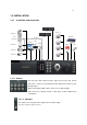
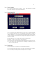
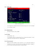
Table Of Contents
- 1. SYSTEM OVERVIEWS
- 1.1 Packing list
- 1.2 Features & specifications
- 1.3 Name, function & connections
- 1.4 INSTALLATION
- 2. Basic operation procedures
- 3. Main Setup screen
- 3.1 Camera Setup menu
- 3.2 Record Setup menu
- 3.3 Event Setup Menu
- 3.4 Playback Setup
- 3.5 Display Setup screen
- 3.6 Network Setup screen
- 3.7 System Setup screen
- 3.8 Backup
- 3.9 System Information
- 3.10 Search Menu
- 3.11 PLAYBACK
- 3.12 Miscellaneous Menu
- 4. DVR-T4IP Client program
- 4.1 Overview of DVR-T4IP
- 4.2 Installation & execution of program
- 4.3 RAMS (Remote Access & Monitoring System)
- 4.3.1 Screen and button
- 4.3.2 Connecting to DVR
- 4.3.3 Channel On/Off
- 4.3.4 UniPlayer link
- 4.3.5 Full-screen display
- 4.3.6 Program setup
- 4.3.7 DVR recording
- 4.3.8 DVR playback search
- 4.3.9 DVR playback search
- 4.3.10 DVR backup
- 4.3.11 DVR Setting
- 4.3.12 Still image Capture
- 4.3.13 Watermark insertion
- 4.3.14 Printing still image
- 4.3.15 Motion picture recording
- 4.3.16 D-Zoom
- 4.3.17 PAN/TILT, ZOOM/FOCUS
- 4.3.18 HDD Information
- 4.3.19 Check the program version
- 4.3.20 S/W upgrade of DVR
- 4.3.21 Close program
- 4.4 UniPlayer
- 4.4.1 Screen and button
- 4.4.2 Search
- 4.4.3 Searching by directory
- 4.4.4 Still Image Capture
- 4.4.5 Input water mark
- 4.4.6 Printing still image
- 4.4.7 D-Zoom Function
- 4.4.8 Moving picture file playback, playing, pause, temporarily pause, move by interval of frame, fast forward Playing
- 4.4.9 Water mark drawing
- 4.4.10 Panorama
- 4.4.11 Check the program version.
- 4.4.12 Close Program
- 4.5 MultiViewer
- 4.6 Quick Installer
- 5. Appendix
22
1.4.1.3 Audio : support or not support
Use IN for a Line input and OUT for speaker output.
1.4.1.4 RS-232
Use this connector to connect RS-232 cable to the serial port on your PC to control the
DVR or to perform Quick Installation.
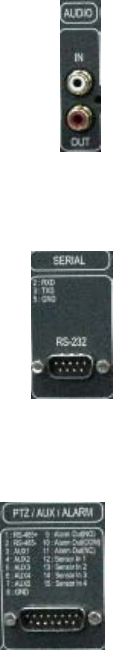
1.4.1.5 PTZ/AUX/ALARM
1.4.1.5.1 RS-485+, RS-485-
DVR-T4IP uses RS-485 protocol to control PTZ Receiver, Speed Dome, and Auto-focus
camera. Be sure to match the polarity.
1.4.1.5.2 AUX 1~5
AUX Port consists of 2 input ports (AUX 1,2) and 3 output ports (AUX 3,4,5) and the function
of each port is selectable according to user’s purpose, user’s access to external DVR, or
controllers using the supplied DB-15 connector.
1.4.1.5.3 Alarm Out (NO, COM, NC)
The Alarm output is activated using a relay contact point when an alarm event occurs for the
duration of the alarm event.
Select from Normal Open Relay or Normal Close Relay.
N.O. (Normal Open) is disconnected from COM during normal status and connected to COM
during alarm event. N.C (Normal Close) is connected from COM during normal status and
disconnected to COM during alarm event.