
Manual


11/56
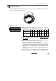
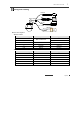
DIP Switch Setup
Before installing the camera, set
up the DIP swit
ch to configure
the
camera ID
and the communication protocol.
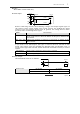
Camera ID Setup
ON
ON
1 2 3 4 5 6 7 8
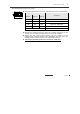
ID numbers of cameras are set up with binary
numbers. See the examples shown below.
Pin
1
2
3
4
5
6
7
8
Binary Value
1
2
4
8
16
32
64
12
8
ex) ID=5
on
off
on
off
off
off
off
off
ex) ID=10
off
on
off
on
off
off
off
off
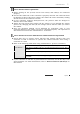
The camera ID range is “1~255”. Camera ID must
not be “0”!
The factory default of the camera ID is “1”.
Match the camera ID with the Cam ID setting of your
DVR or Controller to control the camera.
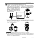
If you are connecting a single camera to a controller,
terminate the camera. When connecting more than
one camera to a single controller, terminate the last
camera on the communication line. The last camera
means the camera farthest in cable length from the
controller.
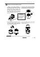
Note that the total length of the communication
cable between a controller and the camera(s) on the
INSTALLATION
2