
Manual


18/56
Internal
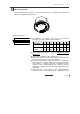
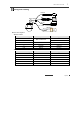
OUT 1
AC or DC
LOAD
Video
Use BNC coaxial cable only.
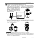
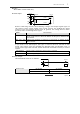
Alarm Input
Before connecting sensors, check driving voltages and output signal types of
the sensors. Since output signal types of the sensors are divided into Open
Collector type and Voltage Output type in general, the wiring must be done
properly after considering those types.
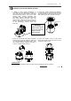
Signal
Description
IN COM+
The electric power source to drive input circuit. Connect the (+) wire of
electric power source to drive the Sensors to this port as shown in the
above circuit.
IN1
-
, IN2
-
, IN3
-
Connect the outputs of sensors to each port as shown in the
above circuit.
If you want to use Alarm Input, the types of sensors must be selected in OSD
menu. The sensor types are divided into Normal Open and Normal Close. If
wrong sensor types are selected, alarms should be activated reversely to sensor
inputs.
Normal Open Output Voltage is high state when sensor is activated
Normal Close Output Voltage is high state when sensor is not activated
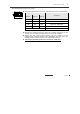
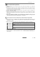
Relay Output
The maximum loads are as follows.
Power Type
DC
Power
AC
Power
Maximum Load
MAX.
DC 24V, 1A
MAX.
AC
125V, 0.5A
IN COM+
+5V~12V
IN 1-
IN 3-
+
+
-
-
+
-
Internal
Sensor 1
Sensor 3
INSTALLA
T
ION
2