Speco Technologies IP Camera User’s Manual IP Camera User’s Manual (Version 1.3.
Speco Technologies IP Camera User’s Manual Introduction We appreciate your purchasing our IP Network Camera. This is a Network Camera with a built-in MPEG-4 CODEC and Streaming Server. It uses an MPEG-4 CODEC as the Video Compression method and has a built-in Streaming Server which allows you to monitor and record real time images in remote places over the Internet.
Speco Technologies IP Camera User’s Manual Important Notes The Network Camera may be damaged by electrical and physical shock Do not try to disassemble the products. Contact or consult the distributor or Head Office for after sale service. There may be no Quality Assurance for the products disassembled arbitrarily. Do not use these products to be connected with life related device like medical apparatus. Do not touch the front lens of the camera.
Speco Technologies IP Camera User’s Manual Contents 1. 2. 3. 4. FEATURE ............................................................................ 8 1.1. PACKAGE ............................................................................................................ 8 1.2. DIMENSION AND CAMERA FEATURES ................................................................... 9 1.2.1. Dimensions .......................................................................................................
Speco Technologies IP Camera User’s Manual 4.2. NETWORK SETTING ........................................................................................... 37 4.3. VIDEO SETTING ................................................................................................. 38 4.3.1. Video Setting ............................................................................................................................. 38 4.4. COLOR SETTING .......................................................
Speco Technologies IP Camera User’s Manual 5.3. USE OF IP SETTING UTILITY.............................................................................. 99 5.4. USE OF SERVICE SERVER ................................................................................ 101 5.4.1. User Registration .................................................................................................................... 102 5.4.2. Camera Registration................................................................
Speco Technologies IP Camera User’s Manual 1.
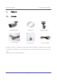
Speco Technologies 1. Feature 1.1. Package IP Camera User’s Manual IP/Network Camera Software CD Cross LAN Cable Accessory Pack Quick Install Guide Power Lead Cable Package of Products is composed of main body of product, Software CD (NVR Program, IP Utility, Product Manual, NVR Manual) , Quick Install Guide, Cross LAN Cable, Accessory Pack, Power Lead Cable. Please check before starting installation.
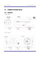
Speco Technologies IP Camera User’s Manual 1.2. Dimension and Camera Features 1.2.1.
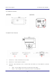
Speco Technologies IP Camera User’s Manual 3) Traditional Camera ② ① ③ 3) Speed Dome Camera ① ② 1) Power Port: Power connection port (12 VDC) 2) VIDEO Port : Video Output Port (BNC) 3) ③ LAN Port: LAN Connection Port ( Connect with LAN Cable for Local Network or Internet Viewing) LINK: LED On (When the product connects with LAN Cable) DATA: LED On (When user connects the product to the Network) 10
Speco Technologies 1.2.2. I. IP Camera User’s Manual Camera Feature Intensifier Cameras (Not available with IP-T5) 1) SLC ( Speco Light Compensation ) : When the image is in front of strong background lighting, your camera allows you to get a clear image. 2) Intensifier: 1/3 inch double density CCD and digital processor permit high quality pictures to be captured in very low light conditions.
Speco Technologies IP Camera User’s Manual 16) Camera OSD control with client program 17) Super Day/Night Function with Power Sensor-up engine 18) Intelligent Pan/Tilt Controlling 19) High-frame rate of up to 30fps at 704x480 size image 20) 4 selectable image sizes – D1,Half D1,2CIF,CIF 21) Simultaneous access up to 20 users 22) Intelligent motion detection and alarm trigger function 23) Pre-alarm recording with ftp server 24) Networking security : Password protection & Encryption 25) A
Speco Technologies IP Camera User’s Manual 2.
Speco Technologies IP Camera User’s Manual 2. Install and Check Video 2.1. Installation 1) Connect the IP Camera to the PC by LAN cable (Crossover Cable) 2) Supply power to the camera using a 12 volt DC regulated power supply. 3) Wait approximately 2 minutes until the Link/LED light comes on. 2.2. Video Check Basic network setting value of the camera is to be: IP Address: 192.168.1.7 Subnet Mask: 255.255.255.0 Gateway: 192.168.1.
Speco Technologies 1) IP Camera User’s Manual Set IP Address, Subnet Mask and Gate-way of User’s PC with 192.168.1.50, 255.255.255.0 and 192.168.1.1 as shown on [Fig. 2-1]. Fig. 2―2 Web Browser Input 2) Run Web Browser as [2-2] and input 192.168.1.7 in URL and click “Enter”, then [2-3] is shown. In case [2-3] does not appear, re-set Hardware (Reset Button in Camera) to reboot and run Web Browser, input 192.168.1.7 in URL line and click “Enter” . Fig.
Speco Technologies IP Camera User’s Manual (1) Fig. 2―4 User login 4) Input ID and Password on [Fig. 2-4] to see Video.
Speco Technologies IP Camera User’s Manual Fig. 2―5 ActiveX Download 9) Upon installation, Web Viewer [Fig. 2-6] appears and the image of the Camera can be seen. Fig. 2―6 Web Viewer 10) After checking proper operation as seen on [Pic 2-6], go onto the next Chapter (3) Basic Setting. 11) Refer to (5) Basic Use’ to see the details of how to use Web Viewer.
Speco Technologies IP Camera User’s Manual 3.
Speco Technologies IP Camera User’s Manual 3. Basic Setting 3.1. Check Network and Installation Type This Chapter is for basic setting of THE CAMERA. To install Hardware of the Network Camera, basic understanding of Networking is required. Please refer to Chapter 6 in case knowledge of Network Environment is required. There are 2 ways to install Hardware.
Speco Technologies IP Camera User’s Manual 3.2. Installation without IP sharing device (Router) 3.2.1. Static IP Setup 1) After checking Video in ‘Video Check’, go to the next step. 2) Connect THE CAMERA to PC with LAN Cable (Crossover Cable). 3) Cable connection and Network Setup should be same as shown in ‘2. Install and Video Check’. 4) Run Web Browser and input 192.168.1.7 in URL and click ‘Enter’, then [Fig. 3-1] will appear. Fig.
Speco Technologies 6) IP Camera User’s Manual Put ‘admin’ in ID and Password line, click ‘Login’, then [3-3] ‘Administrator's Page’ will be shown. (ID, Password of THE CAMERA is preset as admin/admin in Administrator’s Page. Change Administrator’s ID and Password in General Setting of ‘4. Expert Setting’ Fig. 3―3 Administrator’s Page 7) Click “Network Setting’ in left menu on [3-3], [3-4] appears.
Speco Technologies IP Camera User’s Manual Fig. 3―4 Network Setting 12) Click ‘Click Here’ upon appearing of IP Change Window of [3-5]. 13) IP Change loading Page appears as [3-6], the Main Page of changed address is connected. (Note: You may not find the main page of changed address under Cross Cable connection, but IP has been changed.
Speco Technologies IP Camera User’s Manual Fig. 3―6 IP Change loading Page 14) Remove LAN Cable (Cross Cable) connected between THE CAMERA and PC. 15) Connect THE CAMERA to Network with LAN Cable (Straight Cable). 16) Connect PC to Network with LAN Cable (Straight Cable).. 17) Set up IP Address, Subnet Mask and Gateway of PC according to the Network environment.
Speco Technologies 4) IP Camera User’s Manual Go to Network Setting Page of Administrator’s Page as per 4), 5), 6), 7) of ‘Static IP Setup’. Fig. 3―7 Network Setting 5) Click on ‘Dynamic IP Address’ in ‘IP Setting’. 6) Click ‘Save’ Button. 7) Upon completion of setting, close the Web Page and find IP of THE CAMERA in ‘IP Utility’ program provided with Proprietary Viewer (see ‘5. Basic Use’) 8) If the IP is found, THE CAMERA has been given an IP.
Speco Technologies IP Camera User’s Manual connect to THE CAMERA by Domain Name (Server Name) allocated to THE CAMERA. For example, run Web Browser and input Domain Name allocated to THE CAMERA in URL. In http://IPXXXXX.ipcam4u.net, ‘IPXXXXX’ is to be Name of Server registered in Service Server by user. If the initial page is shown as [3-8], check Video of THE CAMERA referring to ‘2. Install and Video Check’. If Video is seen, set up is properly done. Fig. 3―8 Initial Page of THE CAMERA 3.3.
Speco Technologies 7) IP Camera User’s Manual DNS Address should be input. In case THE CAMERA is installed under IP Sharing Device, input local IP of Router in 2 nd DNS Server Address. 8) Click ‘Save’ Button of [3-9] to save the set value. Fig. 3―9 Network Setting 9) Click ‘Click Here’ upon appearing of IP Change Window of [3-10]. 10) IP Change loading Page appears as [3-11], the Main Page of changed address is connected.
Speco Technologies IP Camera User’s Manual Fig. 3―10 IP Change 11) It is connected to the new IP set up, in 20 seconds after window of [3-11] appears. 12) Check Video of THE CAMERA referring to ‘2. Install and Video Check’ as soon as it is connected to the new IP. 13) Go to Network Setting Page of Administrator’s Page as per 4), 5), 6), 7) of IP Setup’. Fig. 3―11 IP Change loading Page Fig.
Speco Technologies 14) IP Camera User’s Manual Set Port in Port Setting Page of [3-12]. It is required to set each different Port for many THE CAMERA Network Cameras under 1 Router. 15) Click ‘Save’ Button to save set value. 16) Remove LAN Cable (Crossover Cable) connected between THE CAMERA and PC. 17) Connect THE CAMERA to Network with LAN Cable (Straight Cable). 18) Connect PC to Network with LAN Cable (Straight Cable).
Speco Technologies IP Camera User’s Manual connect to THE CAMERA by Domain Name (Server Name) allocated to THE CAMERA. For example, run Web Browser and input Domain Name allocated to THE CAMERA in URL. In http://IPINTB1.ipcam4u.net , ‘IPINTB1’ is to be Name of Server registered in Service Server by user. If the initial page is shown, check Video of THE CAMERA referring to ‘2. Install and Video Check’. If Video is seen, set up is properly done. 3.4.
Speco Technologies IP Camera User’s Manual 4.
Speco Technologies 4. IP Camera User’s Manual Expert Setting After registration of THE CAMERA in Service Server (refer to ‘Use of Service Server’ of ‘‘ 5. Basic Use’’, connect to THE CAMERA by Domain Name (Server Name) allocated to THE CAMERA. (For example, run Web Browser and input Domain Name allocated to THE CAMERA in URL. In http://ipcam4u.
Speco Technologies IP Camera User’s Manual Fig.
Speco Technologies 4.1. IP Camera User’s Manual General Setting Fig. 4―3 General Setting 4.1.1. Title Setting Fig. 4―4 Title Setting Server title is to be English without space. Click ‘Save’ Button to save title after input name.
Speco Technologies 4.1.2. IP Camera User’s Manual Administrator’s ID and Password Change ※ Cautions : Change Administrator’s ID and Password and do not disclose the information to others. Administrator’s ID and Password should be English, within 20 characters, without space. Click ‘Save’ Button to save the changed value after change Administrator’s ID and Password. Fig. 4―5 Administrator’s ID and Password Change Remember Administrator’s ID and Password.
Speco Technologies IP Camera User’s Manual Fig. 4―6 User Registration 4.1.4. User List and Delete Fig. 4―7 User List User list is available on clicking ‘List Users’ on [4-7], to check list and delete user ID in [4-8]. User ID ‘guest’, ‘PTZ’, ‘audio’, ‘Iaudio’, ‘PC Audio’, ‘root’ has be pre-registered as basic user ID on ex-factory. Fig. 4―8 User List 4.1.5. Skip Login (Automatic Monitoring) Fig.
Speco Technologies 4.1.6. IP Camera User’s Manual Time Zone Setting This is to set Time zone of location where THE CAMERA is to be installed, to set up local time in case of monitoring from different time zone area. Select one of time zone in ‘Set Time Zone’ and save. Fig. 4―10 Time Zone Click ‘Display’ in [4-10] to see current time set in THE CAMERA. Fig. 4―11 Current Time View In case THE CAMERA does not keep correct time, click ‘Update’ Button to get new time information from set time zone. 4.1.
Speco Technologies 4.1.8. IP Camera User’s Manual Select Language This is to select language to be displayed in all Web Pages such as Administrator’s Page, Web Viewer and Main Page of THE CAMERA. Fig. 4―13 Select Language It supports both English and Japanese. Click ‘Save’ Button to save the set value after select the Language.
Speco Technologies 4.3. IP Camera User’s Manual Video Setting Fig. 4―14 Video Setting 4.3.1. Video Setting Select and tick on the Channel to use, input Video format (NTSC or PAL), Compressed resolution, Bit rate, Frame rate, Key frame. Video setting can be done automatically by pressing ‘High’, ‘Normal’, ‘Low’ according to the Network Speed at which THE CAMERA is installed. Fig.
Speco Technologies 4.4. IP Camera User’s Manual Color Setting This is to adjust color of channel. Fig. 4―17 Display Color Setting Upon adjustment of color on [4-17], then click ‘Save’ to save the setting value. In case to return to default, click ‘Default’ to go to default. Even in this case, it is required to click ‘Save’ Button to save the setting value. 4.5. Alarm Setting 4.5.1.
Speco Technologies IP Camera User’s Manual Fig. 4―18 Alarm Setting Designate condition to drive Event in ‘Alarm Condition’, such as Sensor Event, Motion detection Event or Sensor + Motion detection Event, If Sensor Event is selected, make Sensor settings Upon event situation after setting on ’Enable’ in ‘Alarm’ of ‘Alarm Event’, Event is to be transmitted to user’s Viewer and inform detection of Event, with flickering on screen and alarm sound. (refer to 5. Basic Use).
Speco Technologies 4.5.2. IP Camera User’s Manual Alarm Event Test Click ‘Test’ of [4-18], THE CAMERA will work as if Alarm has happened. In case selected ‘Alarm Style ->’Alarm Server’, Event is to be notified to Alarm Server and is to recorded into the recorded file (10 seconds before and 50 seconds after Event), and to be sent to Alarm Server. In case selected to use user FTP Server, the recorded file (10 seconds before and 50 seconds after Event) is to be saved in FTP Server.
Speco Technologies IP Camera User’s Manual Remote Control: Local Control: to control Relay through Internet using Viewer Relay is on during ‘Duration’ time upon Event on Sensor, then is off. Remote & Local Control: Control Relay through Internet using Viewer. To be ON during ‘Duration’ time upon event on Sensor, then to be OFF. 4.7. Motion Area Setup (1) Motion Area Set: Press the set button. Place the mouse curser on this area and drag it out to the desired area.
Speco Technologies 4.8. IP Camera User’s Manual Camera Setting(support for IP-SD10X) Fig. 4-20 Camera Setting It is available to pre-set Pan/Tilt/Zoom Cameras. Preset Setting is available up to 20, but may be less than 20 for some model of Camera. (1) OSD Menu: to activate OSD Menu. (2) Preset No: to select the Preset Number to set up. (3) Preset SET: ‘SET’ button is to set the current coordinate as preset location with name recorded by user.
Speco Technologies 4.9. IP Camera User’s Manual Homepage Update Fig. 4―21 Homepage Update Homepage Update function is for user to upload the main page of THE CAMERA onto user’s Homepage. User’s Homepage is composed of 3 files, index.html, top.htm, main.htm. The file for user to use is main.htm. After making Web Page (main.htm) and save it as file name of main.htm, upload by the function of ‘Homepage Update’, then main.htm page is to be the 1st main page of THE CAMERA.
Speco Technologies IP Camera User’s Manual 4.10.1. Remote Upgrade Fig. 4―22 Firmware Update Address of ‘Update Server Address’ in [4-22] is set as ‘ipcam4u.net’. Check ‘Current Software Version’ in ‘Current Version’ of [4-22] and go ahead with update if current version is lower than latest version. Upon clicking ‘Update’ button in [4-22] ‘Remote Update’, [4-23] will appear. Fig.
Speco Technologies IP Camera User’s Manual Fig. 4―24 Firmware Download ‘Downloading’ message will be shown until completion of Update as [4-24] (it may take time according to Network situation). Upon completion of upgrade, there appears message showing upgrade result. [4-25] is the message showing that upgrade has been correctly done. Click ‘Restart’ in ‘System Restart’ to restart System of THE CAMERA. Fig.
Speco Technologies IP Camera User’s Manual user keep finding [4-27] or can’t upgrade, contact head office of Speco Technologies Fig. 4―27 Upgrade Server Connection Error 4.10.2. System Re-booting This is the function to re-boot Inner Software of THE CAMERA. Click ‘Restart’ on [4-41] ‘System Restart’ to reboot all inner program of THE CAMERA.
Speco Technologies 4.11. IP Camera User’s Manual Factory Reset 4.11.1. Reset Button Press reset button for 1sec to be operated.(Red Circle) Bullet Camera Dome Traditional Camera Camera Fig. 4―28 Factory reset button 4.11.2. In reset of Factory default Changed to [192.168.1.7] of IP Address. Changed to [192.168.1.1] of Gateway. Changed the Server Login Port No. to “Default”. Changed Web Admin Password to initial data. Initialized DNS Number.
Speco Technologies IP Camera User’s Manual 5.
Speco Technologies IP Camera User’s Manual 5. Basic Use 5.1. Use of Web Viewer Fig. 5―1 Web Viewer Table. 5-1 Definition of Web Viewer Button Function Display Screen reduced by 50%. Display Screen at 100%. Double-clicking mouse on enlarged screen has the same function. Enlarge Video of a channel to 640 x 480. Double-clicking in a selected channel has the same function. Enlarge Video of a channel to full screen Capture a selected channel into a BMP file Select Relay to control.
Speco Technologies IP Camera User’s Manual Relay ON Relay OFF Select Preset to control Select Tour to control Select Pattern to control Move to the selected Preset/Tour/Pattern. Preset Tour. Move to preset location in regular sequence from No. 1 up to 200. Move to next one after 5 seconds pause on a preset location. Display Camera Menu functions of Intensifier Cameras While pressing the mouse in the direction, P/T, Camera moves. Unpressing mouse makes Camera stop.
Speco Technologies IP Camera User’s Manual Table 5-2 Definition of Web Viewer Key Board ③ ① ⑥ ⑥ ③ ⑤ ④ ② ② ③ ④ ‘space ’Key’ Enlarge / reduce Screen Number Key’ Preset Move Function, The Number represents the Preset Number 20 Preset is controlled by Key Board Key Board 1 ~ 0 : Preset 1 ~ Preset 10 Key Board q ~ p : Preset 11 ~ Preset 20 ‘Direction Key’ Pan/Tilt of Camera Pressing on the direction Key makes Camera move to the direction.
Speco Technologies 5.2. IP Camera User’s Manual Use of OSD (Not available with IP-T5) The OSD menu of this camera can be controlled by Web Viewer. Please refer to the ‘1.2.2 Camera Feature’ for OSD function. 5.2.1.
ALARM LANGUAGE [NEXT PAGE] SAVE AND EXIT PATTERN ALARM SECTOR EXIT 54 : 200°/S 10 : AWB MODE WB MODE EXIT PRESET ID: OFF/ON SECTOR ID: OFF ON COORDINATE:ON/OFF [SYSTEM STATUS] [INITIALIZATION] [PREVIOUS PAGE] [PREVIOUS PAGE] CAMERA ID: OFF/ON OSD DISPLAY EXIT EXIT SAVE SAVE : PELCO D,P EXIT SAVE ALARM ACT SECTOR SET [PRIVACY CLEAR] [PATTERN CLEAR] [LOAD OPTIMIZED DEFAULT CAMERA MODULE: SDM100 [PREVIOS PAGE] [REVIOUS PAGE] [SECTOR CLEAR] UPGRADED DATE: 06.
Speco Technologies IP Camera User’s Manual 3) WDR Camera (IP-WDRB1) SPECO MAIN MENU PRESETS DEFAULT / INDOOR / OUTDOOR / CUSTOM SET UP ID DISPLAY ID : (OFF / ON) CAMERA ID : 8 CHARACTER ID POSITION : (UP-LEFT / UP-CENTER / UP-RIGHT DOWN-LEFT / DOWN-RIGHT) LENS SELECT DC MANUAL WDR AUTO OFF MANUAL : (WDR BIAS Range -20 to 20 / WDR RANGE 0 to 36) WB CONTROL ATW(Range 2K~11K) AWB MANUAL (Range 2K ~11K) LOW LIGHT SLOW SHUTTER : (SHUTTER LIMIT Range OFF~X32 / AGC CONTROL Range 0 to 60) AUTO D/N SPE
Speco Technologies 5.2.2.
Speco Technologies 5.2.3. IP Camera User’s Manual Operating Camera OSD Menu (Intensifier Cameras) 1. Press the SET button to access the SETUP mode. SET UP menu is displayed on the monitor screen. 2. Select the desired feature using the UP or DOWN button. Each time you press the UP or DOWN button, the arrow indicator moves up or down. Move the arrow indicator to the desired feature item. 3. Change the status of the selected feature using the LEFT or RIGHT button.
Speco Technologies IP Camera User’s Manual 1) Setting up the LENS Select the lens pressing the RIGHT button. ① On the SETUP menu screen, move the arrow indicator to the lens using the UP or DOWN button. ② Select the desired feature using the LEFT or RIGHT button.
Speco Technologies IP Camera User’s Manual ▶When DC LENS selected, press SET button to control the BRIGHTNESS.
Speco Technologies IP Camera User’s Manual 1) Shutter status and speed control You can control brightness of the screen by the shutter speed. ① Press the SET button to display the setup menu and move the arrow indicator to ‘SHUTTER’ using the UP or DOWN button. ② Set ‘SHUTTER’ to the desired mode using the LEFT or RIGHT button. ▶ OFF : Deactivation ▶ FLK(1/100) : Flicker mode (When WDR is on, the image can flicker a little.
Speco Technologies IP Camera User’s Manual ▶MANUAL : When setting shutter speed manually.
Speco Technologies IP Camera User’s Manual ▶ESC : You can control the BRIGHTNESS.
Speco Technologies IP Camera User’s Manual 3) SLC (Speco Light Compensation) - BACKLIGHT A built-in SR chip provides intelligent light level control to overcome severe Backlight conditions. ① Press the SET button to display the SETUP menu and move the arrow indicator to ‘BACKLIGHT’ using the UP or DOWN button. ② SET ‘BACKLIGHT’ to the desired mode using the LEFT or RIGHT button.
Speco Technologies IP Camera User’s Manual 3) AUTO GAIN CONTROL (AGC) AGC is to get bright picture. Higher GAIN level, getting brighter screen. But you can get noise increase. ① Press the SET button to display the SETUP menu and move the arrow indicator to ‘AGC’ using the UP or DOWN button. ② SET ‘BACKLIGHT’ to the desired mode using the LEFT or RIGHT button.
Speco Technologies IP Camera User’s Manual 5) WHITE BALANCE (WHITE BAL.) For color control on the screen, use ‘WHITE BALANCE’ function. ① Press the SET button to display the SETUP menu and move the arrow indicator to ‘WHITE BALANCE’ using the UP or DOWN button. ② Set ‘WHITE BAL.’ to the desired mode using LEFT or RIGHT button. ▶ ATW (Auto Tracking White Balance) : When color temperature is 2400~12000K, select this mode. (ex.
Speco Technologies IP Camera User’s Manual ▶MANUAL : To fine adjust, select the Manual mode. You can increase or decrease the red or blue factor while monitoring the difference on the screen. Set to ‘MANUAL’ mode and press the SET button. Increase or decrease the value for RED(R-Gain) and BLUE(B-Gain), watching the color of the picture, and press the SET button when you obtain the best color. Notes Proper White Balance may not be obtained under the following conditions in these cases select the AWC mode.
Speco Technologies IP Camera User’s Manual 6) Digital Noise Reduction (Dynamic Noise Reduction) DNR is to reduce the noise on the screen. ① Press the SET button to display the SETUP menu and move the arrow indicator to ‘DNR’ using the UP or DOWN button. ② SET ‘DNR’ to the desired mode using the LEFT or RIGHT button.
Speco Technologies IP Camera User’s Manual 7) INTENSIFIER Allows you to get clear images with this function under night or low light conditions ① Press the SET button to display the SETUP menu and move the arrow indicator to ‘Intensifier’ using the UP or DOWN button. ② SET ‘Intensifier’ to the desired mode using the LEFT or RIGHT button. ▶AUTO : When your camera is under night or low-lighting level, select this mode.
Speco Technologies IP Camera User’s Manual 8) NEXT PAGE ① Press the SET button to display the SETUP menu and move the arrow indicator to ‘Intensifier’ using the UP or DOWN button. ② SET ‘Intensifier’ to the desired mode using the LEFT or RIGHT button. (A) CAMERA TITLE ① Press the SET button to display the SETUP menu and move the arrow indicator to ‘CAMERA TITLE’ using the UP or DOWN button. ② SET ‘ON’ using the LEFT or RIGHT button.
Speco Technologies IP Camera User’s Manual ③ Press SET button to access the SETUP mode. ④ You can enter up to 15 characters. a. Move the cursor to character-enter location by using the LEFT or RIGHT button. b. Select the desired character by using the UP or DOWN button. c. Press SET button to confirm the blinking character. The first character is saved and the cursor in the bottom of the screen moves to the next position. d. Repeat steps a, b and c until you create the full name you want. e.
Speco Technologies IP Camera User’s Manual B) COLOR You can choose color and B/W mode electronically. (OPTION) ▶ ON : color mode ▶ OFF : B/W mode ▶ AUTO : generally color mode, B/W mode in low luminance. Notes OSD Key may not work for 3 seconds when the COLOR/ BW mode is changed.
Speco Technologies IP Camera User’s Manual C) SYNC Two SYNCHRONIZATION modes are available… INTERNAL and EXTERNAL LINE-LOCK. In LINE-LOCK mode, the camera syncs to the 60 Hz phase. ① Press the SET button to display the setup menu and move the arrow indicator to ‘SYNC’ using the UP and DOWN button. ② SET to the desired mode using the LEFT or RIGHT button. ▶ INT : Internal synchronization ▶ L/L : If you choose ‘L/L’, you can adjust the desired phase. - Press the SET button.
Speco Technologies IP Camera User’s Manual D) PRIVACY To mask an area that you want to be private. ① Press the SET button to display the setup menu and move the arrow indicator to ‘PRIVACY’ using the UP and DOWN button. ② SET ‘PRIVACY’ to the desired mode using the LEFT or RIGHT button. ▶OFF : Deactivation ▶ON : PRIVACY mode activated -Press the SET button. -Move the arrow indicator to area you want to mask. -Set ‘ON’ using LEFT or RIGHT button.
Speco Technologies IP Camera User’s Manual E) REVERSE ① Press the SET button to display the setup menu and move the arrow indicator to ‘REVERSE’ using the UP and DOWN button. ② SET ‘REVERSE’ to the desired mode using the LEFT or RIGHT button. ▶OFF : Deactivation ▶ON : Make a reverse turn to RIGHT or LEFT.
Speco Technologies IP Camera User’s Manual F) DETAIL ① Press the SET button to display the setup menu and move the arrow indicator to ‘DETAIL’ using the UP and DOWN button. ② SET ‘DETAIL’ to the desired mode using the LEFT or RIGHT button. ▶OFF : Deactivation ▶ON : DETAIL control mode (level 0~31) When the level is up, the sharpness will increase. Control this level to get your best picture quality. If the level is too high, you can get an unnatural image with video noise.
Speco Technologies IP Camera User’s Manual G) DEFAULT : Use to reset your camera to FACTORY DEFAULT SETTING.
Speco Technologies 5.2.4. IP Camera User’s Manual Operating WDR Camera OSD Menu (IP-WDRB1) OSD MENU CONTROL CENTER KEY - Used to access menu mode. Also used to confirm the setting UP / DOWN KEY - Used to choose the desired menu selection. LEFT / RIGHT KEY - Used to choose the desired menu feature adjustment. OSD MENU ENTER / EXIT A. OSD MENU ENTER • Push Center Key for 2 seconds B. OSD MENU EXIT • Press EXIT Menu from Main Menu • If Pressing Set Key for 2 seconds from Main Menu appears.
Speco Technologies IP Camera User’s Manual - ON :The ID name will displayed in the monitor. - OFF : The name will not displayed in the monitor. • CAMERA ID : Enter up to 8 characteristic. • ID POSITION : Select the screen position of the camera ID. C. LENS • DC : Use When using DC lens. • MANUAL : Use When using Manual lens. D. WDR • WDR (Wide Dynamic Range) : You can adjust the desired WDR BIAS from -20 to 20 and WDR RANGE from 0 to 36 E.
Speco Technologies IP Camera User’s Manual • SHARPNESS : ON (You can adjust the desired Sharpness form -8 to 8) or OFF H. EXIT MENU • EXIT NO CHANGES : No change • SAVE NEW AND EXIT : Save change • RESTORE FACTORY SETTINGS : Factory default • RELEASE VERSION I. PREVIOUS PAGE • PREVIOUS PAGE : Return page 5.2.5.
Speco Technologies IP Camera User’s Manual A. Dome Setup To enter Dome setup, use the five keys right to move when cursor on dome setup. DOME SET CAMERA ID : CAM1□□□□□□□□□□□□ RECOVER : OFF MANUAL SPEED : 100°/S AUTO FLIP : OFF ZOOM SPEED : FAST ALARM : DISABLE LANGUAGE : ENGLISH [NEXT PAGE] SAVE AND EXIT EXIT A-1. DEFAULT SETTING DOME SET - CAMERA ID To set camera ID, select up to 16 characters using Five keys to the left or right.
Speco Technologies IP Camera User’s Manual select ON or OFF. The default setting is OFF. A-5. DOME SET – ZOOM SPEED Zoom speeds are selectable FAST or SLOW mode. Move five keys to the right direction for selecting FAST or SLOW. The default setting is FAST. A-6. DOME SET – ALARM All alarms are available after set as ENABLE Mode. Move five keys to right or left direction for selecting ENABLE/DISABLE. The default setting is DISABLE. A-7.
Speco Technologies IP Camera User’s Manual 5.2.1. OSD MAIN MENU TABLE (PAGE 54) The default setting is BLANK. ENTER PASSWORD BY ENTERING PRESET CODE PASSWORD *** CONFIRM *** Press any number from 001~255 with preset button on password blank and again it on confirm blank. Then “CONFIRMED” is displayed on the monitor and the menu will go back to the previous page automatically.
Speco Technologies IP Camera User’s Manual OSD DISPLAY CAMERA ID PRESET ID SECTOR ID COORDINATE [PREVIOUS PAGE] A-8-4. : : : : OFF OFF OFF ON DEFAULT SETTING DOME SET – [NEXT PAGE] – [SYSTEM STATUS] This page shows the information of this camera. SYSTEM STATUS PROTOCOL : PELCO BAUD RATE FIRMWARE VER. UPGRADED DATE CAMERA MODULE [PREVIOUS PAGE] D, P : 2400 BPS : 2.00 : 06.
Speco Technologies IP Camera User’s Manual INITIALIZATION [TOUR CLEAR] [PRESET CLEAR] [SECTOR CLEAR] [PRIVACY CLEAR] [PATTERN CLEAR] [LOAD OPTIMIZED DEFAULT] [PREVIOUS PAGE] - To clear memorize any data, move five keys to the right direction when cursor is on each item. TOUR CLEAR TOUR CLEAR ARE YOU SURE? YES NO Press FOCUS NEAR button when the cursor is at YES in order to clear memorized data.
Speco Technologies A-9. IP Camera User’s Manual DOME SET – [NEXT PAGE] – SAVE AND EXIT To saving the memorized data and escape this page, move five keys to the right direction when cursor is at SAVE AND EXIT. A-10. DOME SET – [NEXT PAGE] – EXIT In order not to save any data and wants to escape this page, move five keys to the right direction when cursor is at EXIT B.
Speco Technologies B-3. IP Camera User’s Manual CAMERA SET – APERTURE Aperture enhances picture details by increasing gain of the caemra and sharpens the edges in the picture. The default seeting is 10. (the aperture level is from 01 ~ 15) (10X Zoom) B-4. CAMERA SET – D ZOOM Move five keys to the right direction in order to set as ON, if Digital Zoom is necessary at install field. The default setting is OFF. (10X Zoom) B-5.
Speco Technologies IP Camera User’s Manual (10X Zoom) B-9. CAMERA SET – DSS MODE (DIGITAL SLOW SHUTTER) If DSS turns on, digital slow shutter is working. Per second, the electronic shutter will remain open to receive some more lighting. (10X Zoom) B-10. CAMERA SET – EXIT To escape this page, move five keys to the right direction. C. PRESET SET To enter PRESET SET, move five keys to the right direction. PRESET SET PRESET NO :001 PRESET ID :PRESET001------PAN :XXX.XX TILT : XXX.XX SAVE EXIT C-1.
Speco Technologies C-3. IP Camera User’s Manual PRESET – PAN: XXX.X TILT: XX.X Press FOCUS FAR button in order to set preset position then, use the five keys to the position where memorized preset no. is needed. Then press FOCUS FAR button again after setting a preset location. C-4. PRESET – SAVE Move five keys to the right direction when the cursor is at SAVE and then the cursor will be located on Preset ID for the continuous preset No. setting. C-5.
Speco Technologies IP Camera User’s Manual right or left direction CW: Clock wise direction (Default) CCW: Count Clock Wise Direction. D-4. AUTO SCAN – ENDLESS Auto Scan can use endless rotation, move five keys to the right direction in order to select ON. D-5. Otherwise, the default setting is OFF. AUTO SCAN – SPEED User can use auto scan speed from 05°/S up to 35°/S and the default setting is 10°/S D-6.
Speco Technologies IP Camera User’s Manual E. TOUR SET 8 Programmable tours can be set and each tour is available to set up to 64 preset steps. TOUR SET TOUR NO TOUR TITLE TOUR STEP PRESET NO. DWELL TIME SPEED SAVE EXIT : : : : : : 01 TOUR01□□□□□□□□□□ 01 01 03 200°/S DEFAULT SETTING E-1. TOUR SET – TOUR NO. Max. 8 group tour no. set by the five keys are available. E-2. TOUR SET – TOUR TITLE To set tour title, select up to 16 characters using Five keys to left or right.
Speco Technologies IP Camera User’s Manual E-6. TOUR SET – SPEED Each tour step can be set with different tour speed up to 200°/S and it is selectable from 10°/S. Move five keys to the right or left direction to select tour speed. The default setting is 200°/S. E-7. TOUR SET – SAVE To save the memorized data and escape this page, move five keys to the right direction when cursor is at SAVE E-8. TOUR SET – EXIT To escape this page, move five keys to the right direction F.
Speco Technologies IP Camera User’s Manual To set the blocking area, press FOCUS FAR button when the MOVE MODE is appeared. area. Then use the five keys to the user defined area in order to set blocking Then press FOCUS FAR button again to escape from MOVE MODE. To adjust size of blocking area, move five keys to the right or left direction when the cursor is on ACTION. After move mode changed to ADJUST MODE, press FOCUS FAR button in order to adjust the size of blocking area.
Speco Technologies IP Camera User’s Manual Up to 8 programmable user-defined patterns set by the five keys on the Webviewer GUI are available. G-2. PATTERN SET – PATT TITLE To set PATTERN TITLE, select up to 16 characters using Five keys to the left or right.
Speco Technologies IP Camera User’s Manual H. ALARM SET 4 Alarm inputs are available and each alarm is activating to presets, group tours or patterns. ALARM SET ALARM NO : 01 ALARM INPUT: OFF ALARM ACT : 001 SAVE EXIT H-1. DEFAULT SETTING ALARAM SET – ALARM NO. Up to 4 alarms are selectable by using five keys to the right direction when cursor is on ALARM NO. H-2.
Speco Technologies IP Camera User’s Manual * Before activating Alarm, user must set ALARM ENABLE at DOME SET – ALARM – ENABLE (Refer to page 15) I. SECTOR SET Up to 8 programmable sectors are available with 16 characters. This feature is useful to memory the certain location such as parking zone or so on. When camera goes through this area, it shows the letter you memorized. SECTOR SET SECTOR SECTOR SECTOR SECTOR SAVE EXIT Start Position NO : 01 ID : SECTOR01□□□□□□□□ START: XXX.X.XX.X END : XXX.X.XX.
Speco Technologies IP Camera User’s Manual I-4. SECTOR SET – SECTOR END To set SECTOR END angle, press FOCUS FAR button then move five keys to the left or right direction to set the position. To press FOCUS FAR button again is to escape. I-5. SECTOR SET – SAVE After setting the SECTOR position, to save the data, move five keys to the right direction when the cursor is on SAVE. After saving the data, the cursor moves to SECTOR NO.2 automatically to prepare the next SECTOR. I-6.
Speco Technologies IP Camera User’s Manual DIP SW SETTING 5.2.6. Mini Speed Dome camera provides up to 63 camera ID and it’s adjustable ID with 1st~6th of Dip switch Open the camera case, set ID using DIP SW1. * Factory default: Camera ID = 1, PELCO-D Termina Baud Proto ID Set 5.2.7.
Speco Technologies IP Camera User’s Manual 100010XXXX 17 111001XXXX 39 101111XXXX 61 010010XXXX 18 000101XXXX 40 011111XXXX 62 111111XXXX 63 110010XXXX 19 100101XXXX 41 001010XXXX 20 010101XXXX 42 101010XXXX 21 110101XXXX 43 011010XXXX 22 001101XXXX 44 5.2.8. th PROTOCOL th 7 ~8 dip switches are used for Protocol Setting. Factory Default: Pelco-D or Pelco-P ( Auto detection) 5.2.9.
Speco Technologies 5.3. IP Camera User’s Manual Use of IP Setting Utility Upon running IP Setting Utility, the following program is to be displayed. Fig. 5―2 IP Find Click ‘IP Find’ Button to find IP of THE CAMERA on local Network. Fig. 5―3 Display IP The following window shows list of IP along with Web Server Port Number and Model Name of THE CAMERA. Click ‘IP Find’ Button to find IP of THE CAMERA on local Network.
Speco Technologies IP Camera User’s Manual Fig. 5―4 IP Check After finding IP, double-click IP of THE CAMERA to go to the editable Mode as follows. Fig. 5―5 IP Check Input new IP Address, Default Gateway, Subnet Mask, and then input Password of THE CAMERA Administrator and click ‘IP Change’, to set up new IP of THE CAMERA. Upon completion of setting, find new IP and click ‘Ping’ to check whether setting is done, and close the program by clicking ‘End’ button.
Speco Technologies 5.4. IP Camera User’s Manual Use of Service Server Run Web Browser and input http://ipcam4u.net in URL and click ‘Enter’, then [5-6] will appear as follows. Fig. 5―6 Service Server Click the language user want to use.
Speco Technologies 5.4.1. IP Camera User’s Manual User Registration Fig. 5―7 User Login Click ‘Register Now’ in [5-7]. Fig.
Speco Technologies IP Camera User’s Manual Read the Agreement carefully and click ‘Agree’ in case to agree, and go to the next page. Fig. 5―9 User Registration The part marked with (*) is mandatory. User ID is to be double-checked. Then click ‘Log In’. Fig. 5―10 User Registered If [5-10] appears, User Registration has successfully completed.
Speco Technologies IP Camera User’s Manual and password on [5-7] to connect to Service Server. Fig. 5―11 Service Server Log-in Succeeded 5.4.2. Camera Registration Click ‘To register camera’ in [5-11] to go to Camera Registration Page. ① ② ③ ④ Fig. 5―12 Camera Registration Input name of THE CAMERA in ① of [5-12], which will be applied only in Service Server. ② Server Name is to input Domain Name to connect to THE CAMERA.
Speco Technologies IP Camera User’s Manual knowing IP address of THE CAMERA. Domain Name must be unique. Register after checking if it is duplicate or not. ③ is to check whether the Camera is to be open or not. ④ is for the function to connect to THE CAMERA easily by User’s ID and Password registered in THE CAMERA, to monitor or control Video of THE CAMERA on Mobile Phone. (Mobile Phone Users should tick “Enable” and input connection ID and Password.
Speco Technologies IP Camera User’s Manual Fig. 5―14 Camera List [5-14] shows the registered List of THE CAMERA. Upon clicking on ‘Camera Name’ registered in [5-14], [5-15] will show the Camera Information. ‘Time’ is the latest time for THE CAMERA to report to Service Server. Fig. 5―15 Camera Information On clicking ‘Camera Change’ on [5-14], the page of ‘5.3.2 Camera Registration’ to change the information of Camera registered, will appear.
Speco Technologies IP Camera User’s Manual Fig. 5―16 Alarm Log List ‘Alarm Log List’ shows the information of a channel, alarmed time, type of Alarm. It is available to delete the log file. THE CAMERA sends the recorded files, dividing into Video file and Audio files, to Service Server In case there is no recorded file, the message will show ‘No File’. In case the file has not sent to Service Server yet, the message “Uploading” will be shown.
Speco Technologies IP Camera User’s Manual Fig. 5―17 Change User’s Information Save User’s information by clicking ‘To Change Information’ after change user’s information. 5.4.5. Search Camera Fig. 5―18 Search Camera ‘Search Camera’ of [5-18] is the function to see information of THE CAMERA or connect directly to THE CAMERA without user registration in Service Server. Upon clicking ‘Camera Search’ on [518], [5-19] to search Camera will appear.
Speco Technologies IP Camera User’s Manual Fig. 5―19 Search Camera If user want to see information of THE CAMERA by the Address, select ‘Information’ and input MAC Address of THE CAMERA to see information on, and click ‘confirmation’ . Then Information of THE CAMERA will be shown as [5-20]. 5.5. See and Control of Still Image in Mobile or PDA To monitor and control of Still Image of THE CAMERA on Mobile Phone, register in ‘Camera Registration’ of ‘Use of Service Server’ in ‘5. Basic Use’.
Speco Technologies IP Camera User’s Manual Fig. 5―21 Input User ID On user ID input Page [5-21], input user’s ID registered in ‘Use of Service Server ’ of ‘5. Basic Use’. Fig. 5―22 List of Registered Products Select one of the products (Camera or Server) registered by user on[5-22]. Fig. 5―23 Menu Select a item in menu of (1) [5-23].
Speco Technologies IP Camera User’s Manual Fig. 5―24 Pan/Tilt/Zoom Control It is available to see Image and control Pant/Tilt/Zoom/5 Preset. Number Key of Mobile Phone controls Pan/Tilt/Zoom. (2) Relay Control (2 Relay controllable) It is available to control up to 2 Relay. Relay Name and current status ([ON/OFF]) will be displayed. On control of Relay, Image of controlled channel will be shown along with Relay name of the channel, ON/OFF is to be controllable.
Speco Technologies IP Camera User’s Manual It shows the Sensor Name and current status ([Normal/Sensing]). 5.5.2. PDA(WinCE) Run ‘Internet Explorer’ of PDA and input http://ipcam4u.net/pdah5450_eng.htm input in URL to connect to Service Server. Fig. 5―25 PDA Log-in On user ID Input Page [5-25], input user’s ID registered in ‘Use of Service Server ’ of ‘5. Basic Use’ and click ‘connect’ to log in. Fig.
Speco Technologies IP Camera User’s Manual Fig. 5―27 Menu 5.6. Use of NVR Program 5.6.1. Required Specification of PC and OS Item Min. Requirement Recommended Specification CPU Pentium Ⅳ 2.0G Pentium Ⅳ 2.4G or higher Main Memory 256MB 512MB or higher O/S Windows 2000/XP Windows 2000/XP Web Browser I.E 5.0 I.E 5.0 or later Resolution 1,024 * 768 1,152 * 864 Network 100 Base-T Ethernet 100 Base-T Ethernet * 5.6.2.
Speco Technologies IP Camera User’s Manual 6.
Speco Technologies 6. IP Camera User’s Manual Network Environment It is required to follow the recommendation of the environment where THE CAMERA will be installed or the similar environment. 6-1. Private line Environment Usually Company, University, Research center use the leased line. They use many public IP addresses. In order to install THE CAMERA under this environment, select “Static IP Address” in ‘Static IP Setting’ of ‘3. Basic Setting’ and input IP address, subnet mask and gateway.
Speco Technologies IP Camera User’s Manual Web Connection Port : Port 80 TCP Authentication and Control Port : Port 9000 TCP Video Streaming Port : Port 9001 TCP Motion Detectin Control Port : Port 9005 TCP 116
Speco Technologies IP Camera User’s Manual 7.
Speco Technologies 7. IP Camera User’s Manual Appendix Appendix A Basic Setting Table Item Default (Basic Setting) Remarks Network Setting Static IP / Dynamic IP Static IP IP Server Enable IP Address 192.168.1.7 Gateway 192.168.1.1 Subnet Mask 255.255.255.0 Web Connection Port 80 *. Don’t register the same Port. Authentication /Control Port 9000 *.
Speco Technologies IP Camera User’s Manual Appendix B Specification of Products B-1 IP-INTB1 / INTB2 Image Sensor 1/3" Sony Super HAD CCD, 410,000 pixels 811(H)*508(V) 795(H)*592(V) 768(H)*494(V) 755(H)*582(V) 540 TV Lines 0.002 Lux(selectable limit ~ X128) 50dB(Weight On) DC AUTO IRIS VF 2.8~10mm(F1.
Speco Technologies IP Camera User’s Manual B-2 IP-INTD3 / INTD4 Image Sensor 1/3" Sony Super HAD CCD, 410,000 pixels 811(H)*508(V) 795(H)*592(V) 768(H)*494(V) 755(H)*582(V) 540 TV Lines 0.002 Lux(selectable limit ~ X128) 50dB(Weight On) DC AUTO IRIS VF 2.8~10mm(F1.
Speco Technologies IP Camera User’s Manual B-3 IP-INTT5 Image Sensor 1/3" Sony Super HAD CCD, 410,000 pixels 811(H)*508(V) 795(H)*592(V) 768(H)*494(V) 755(H)*582(V) 540 TV Lines 0.
Speco Technologies IP Camera User’s Manual B-4 IP-T5 Image Sensor Total Pixel Effective Pixel 1/3" Panasonic CCD, 410,000 pixels NTSC 811(H)*508(V) PAL 795(H)*592(V) NTSC 768(H)*494(V) PAL 755(H)*582(V) Horizontal resolution 480 TV Lines Minimum Illumination 0.
Speco Technologies IP Camera User’s Manual B-5 IP-WDRB1 Image Sensor 1/3" Pixim ORCA CMOS(Dramatic Dynamic range sensor) NTSC PAL Horizontal resolution Minimum Illumination S/N Ratio Lens Scanning System Synchronization Compression Multi-Streaming AGC Control Electric Shutter Speed Dynamic range Maximum Frame Rate Total Pixel IMAGING 742(H)*552(V) 540 TV Lines 0.08Lux (DSS on) with F1.2 Lens 53dB or more DC AUTO IRIS VF 2.8~10mm(F1.
Speco Technologies IP Camera User’s Manual B-6 IP-SD10X Image Sensor 1/4" Sony Super HAD CCD No. of Pixel 768(H) * 494(V) Horizontal resolution More Than 500TV Lines Minimum Illumination 0.7Lux (50IRE) / 0.02Lux (ICR On) Digital Slow Shutter 2/4/8/16/24/32/64/128/ OFF Lens Optical 10x Optical Zoom(F=3.
Speco Technologies IP Camera User’s Manual Interface 10/100Mbps Current Users Recording@PC Event& Alarm 20 Manual Yes Schedule Yes Motion Detection Yes Sensor event Yes Sensor Trigger/Motion Detection Yes Alarm Notification SMS/E-MAIL/Alarm Sound(Option) Video Output VBS:1.0Vp-p/75 Ohm Dimension 158.8φ (D) * 163.0mm(H) Power Source PHYSICAL DC12V 1.0A Power Consumption (Max.) 12W Max Operational Temperature 0'C ~ 50'C Weight 1.
Speco Technologies IP Camera User’s Manual Check with ‘C-1-2 Network Cable (LAN cable) and cable connection check’. PING Test In case Camera uses Static/Public IP: input “Ping IP address” to command window In case camera uses dynamic/public IP: In this case, user cannot find camera IP of PC and check response. address. So, reset hardware and connect PC with THE CAMERA through cross cable and ping test by “192.168.1.7”.