Quick Start Guide O4B6N
Welcome Thank you for purchasing this network camera! This owner's manual is designed to be a reference tool for your system. Please read this manual carefully before operating the unit and retain it for future reference. Should you require any technical assistance, contact Speco Technologies Tech Support at 1-800-645-5516 Important Safeguards and Warning 1. Electrical safety All installation and operation here should conform to local electrical safety codes.
dampened with a small quantity of neutral detergent. Finally use the dry cloth to clean the device. Please use a professional optical cleaning method to clean the enclosure. Improper enclosure cleaning (such as using cloth) may result in poor IR functionality and/or IR reflection. The grounding holes of the product are recommended to be grounded to further enhance the reliability of the camera.
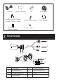
Camera CD Quick start guide 8 screws (PA 4 ×25mm) 1 screw (PWM3 × 5mm) 4 screws (PM 4 × 10mm) Junction box 8 Plastic Screw Anchors Drill Template 4 screw o-rings Overview 32 Overview 3 4 5 1 2 6 7 1 Fixed ring 5 Power connector 2 Mounting base 6 Micro SD card slot 3 Ethernet connector 7 Reset 4 Audio input
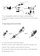
of Wat er-p ro Co nn ec to r DC12V * 1 It is recommended to install the security cap for outdoor installations. * 2 DC 12V power supply is not required if a PoE switch or injector is used to power the camera. ► Connecting Network Cable 1 2 3 ① Loosen the nut from the main element. ② Run the network cable (without RJ 45 connector) through both elements. Then crimp the cable with RJ 45 connector. ③ Connect the cable to the water-proof connector. Then tighten the nut and the main cover.
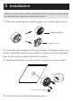
3 Installation * Before you start, please make sure that the wall or ceiling is strong enough to withstand three times the weight of the camera. ① Open the mounting base and the upper cover of the junction box. Mounting Base Upper Cover ② Attach the drill template of the junction box to the place where you want to install the junction box and then rill the screw hole and calbe hole on the wall according to the drill template. ③ Install junction box onto the wall by using the screws provided.
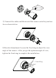
4× 6.6mm PM 4x10mm ⑤ Connect the cables and then i nstall the camera onto the junction box as shown below. ⑥ Bracket Adjustment-Loosen the fixed ring to adjust the view angle of the camera. After you get the optimum angle of view, tighten the fixed ring to complete the installation.
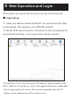
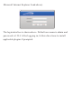
4 Web Operation and Login IP Scanner can search for the device on the local network. ● Operation ① Make sure that the camera and the PC are connected to the same local network. The camera is set to DHCP by default. ② Install IP Scanner from the CD and run it after installation.Or download from https://www.specotech.com/ip-scanner/ O4B6N 5C:F2:07:24:28:9A ③ In the device list, you can view the IP address, model number, and MAC address of each device.
Microsoft Internet Explorer 8 and above). The login interface is shown above. Default user name is admin and password is 1234. After logging in, follow directions to install applicable plugins if prompted.