
User Guide

PUBLIC ADDRESS AMPLIFIER
9
P120FACD/P240FACD
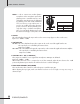
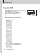
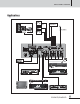
5. OPTIONAL EXTERNAL PAGING UNIT TERMINAL
This unit has the ability to be controlled via an external, zoned paging microphone, which will be available as
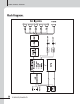
a future option. For reference, here is the pin chart:
6. MUSIC ON HOLD VOLUME
Control the volume level of Music On Hold.
7. EM (EMERGENCY) TERMINALS
When EM switch is connected and pressed in fire or in other emergency cases, EM broadcasting stored in
VOICE IC is outputted. When EM is activated, all the other signals are muted.
8. EXT CHIME
Use these terminals to activate the chime externally.
When the EXT CHIME is selected the ‘CHIME1’, 2 tone chime is activated.
9. EXT MUTE
Use these terminals to mute the signal of the unit externally.
Only EM, RM or Tel-In has priority over the EXT Mute.
10. TEL IN TERMINALS
These terminals can be connected to a telephone exchange system.
When the telephone signal is input, all the other input signals are muted.
11. MUSIC ON HOLD TERMINALS
These terminals output the internally selected source. This is a balanced output.
12. FM ANTENNA
Connect the FM antenna here. Please mount the antenna in an area with good reception.
13. MIC 1 / 2 PRIORITY
Press these switches to give priority to channels 1 or 2.
14. PHANTOM POWER SWITCH
These switches turn the phantom power supply on and off for each channel. When the switch is pushed in,
24V DC power is supplied to pins 2 and 3 of the XLR jack. Use phantom power when using a condenser
microphone which requires an external power supply.
Pin 1: Remote amplifier input signal hot(+) Pin 8: Remote control 5(Speaker 5)
Pin 2: Remote amplifier input signal cold(–) Pin 9: Remote control ground
Pin 3: Signal ground Pin 10: DC +24V
Pin 4: Remote control 1(Speaker 1) Pin 11: Chime Input
Pin 5: Remote control 2(Speaker 2) Pin 12: NC
Pin 6: Remote control 3(Speaker 3) Pin 13: NC
Pin 7: Remote control 4(Speaker 4) Pin 14, 15: NC