Speco Internet Protocol (SIP)H.264 Series Camera Instruction Manual (Version 1.0.0) SIP H.264 Megapixel Cameras SIPMPBVFH & SIPMPDVFH i Speco Technologies 200 New Hwy, Amityville, NY 11701 800-645-5516 www.specotech.
Table of Contents 1. FEATURES....................................................................................................... 1-1 1.1 Package ..................................................................................................................... 1-1 1.2 Dimension and Connector Description ..................................................................... 1-2 2. 1.2.1 Dimensions .......................................................................................................
Profile Upload ..........................................................................................................................2-55 Save & Reboot .........................................................................................................................2-56 Logout ......................................................................................................................................2-56 APPENDIX ...........................................................................
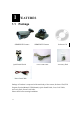
1 1. 1.1 FEATURES Package SIPMPBVFH Camera Quick Install Guide SIPMPDVFH Camera Cross LAN Cable Software CD Accessory Pack Power Lead Cable Package of Products is composed of the main body of the camera, Software CD (NVR Program, Product Manual, NVR Manual), Quick Install Guide, Cross LAN Cable, Accessory Pack, Power Lead Cable. Please check before starting installation.
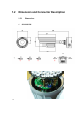
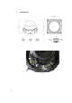
1.2 Dimension and Connector Description 1.2.1 1.
2.
1.2.2 ① ② ③ ④ ⑤ Connector Description 12 Volts DC Power Input Audio Output Audio Input : The SIP Camera supports one audio input and output Ethernet Port : Standard RJ45 connector. Supporting POE. Reset Button (** Please open the case for the Bullet / Dome type camera ) Step 1 : Switch off SIP Camera by disconnecting the power cable. Step 2 : Using a suitable pointed object, press and continue to hold the Reset Button. While continuing to hold the reset button, reconnect the power cable.
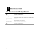
2 2. 2.1 INSTALLATION Recommended PC Specification CPU Core2Duo 2.13GHz and above Memory 2 GB or above Windows XP with SP2 or above. Windows Vista / Windows 2003 / Operating System Windows 7 Internet Explorer 6.0 SP2 and above. Video Resolution SVGA or XGA with 1024x768 resolution CPU Core2Duo 2.
2.2 Preparation before setup To configure your IP device, you have to use Internet Explorer to log in. Before that, your PC’s network settings and the IP device’s IP address must be set up. Make sure all the connections are connected correctly, and then follow the procedures below. 1. Setup your PC network You have to match your PC’s TCP/IP setting with the IP device’s default settings before you can use IE browser to login it. This section tells you how to setup your PC’s TCP/IP settings. 2.
The procedure below is the setup procedure of a PC using Windows XP as its OS. When running an OS other than Windows XP, please refer to the manual included with the OS. 2-7 STEP 1 Start up your PC.
STEP 3 Double-click the "Network and Internet connections" icon.
STEP 5 Click “Local Area Connections”, and then click “Change settings of this connection” in the network Task menu. STEP 6 Click “Internet Protocol (TCP/IP)”, and then click the [Properties] button.
STEP 7 Click the “Use the following IP address” radio button and enter the IP address and the subnet mask. Please set the settings as below. IP address: 192.168. 0.xxx Subnet mask: 255.255.255. 0 (NOTE: xxx should be a number from 1 to 254, but 100 is excepted.) STEP 8 Click the [OK] button and the window dialog box closes.
2.3 Configuring the IP device This section describes how to configure the IP device. The product administrator has unlimited access to all setup windows and normal users can only watch the live image. The IP device is configured under a standard browser (Microsoft Internet Explorer 6.0 or above). Follow the procedures below to configure the IP device. STEP 1: Open a browser STEP 2: Enter the IP address of the IP device. The default IP address is “192.168.0.
2-12
2.3.1 Video Display This section tells you how to view live images via Internet Explorer. Click the [Live] tab to show [Live page]. Refer to the table below for how to configure each setting. Function List Function Full Screen Snapshot 2-13 Description to stretch the preview to full screen. Click the icon You can click “Esc” button on the keyboard to return to previous display. Click the icon “ ” to take a snapshot.
Audio out Click the icon to enable the audio out from PC to IP camera or video server. When it is enabled, your voice will be transferred to the audio out of the IP camera or video server. NOTE: you will need to have a microphone connected to your PC to do that. Media If dual stream mode is enabled, click to select which stream to display (Media 1 or 2). The default is single stream only.
not zoomed-in (no zoom status). Network status Indicates the network state. If the light on the right is green, it means the network is ok. If the light is gray, it means the network is broken. The light on the left is not used DO Setting Click to set DO output level to High. to set DO output level to Low. If your device Click has more than one DO available, each DO is controlled separately.
2.3.2 Date & Time This section tells you how to setup IP device’s date and time settings. STEP 1: Click the [Date & Time] on the “Main Setup page”. The “Date setting page” is displayed as below STEP 2: Configure these settings with reference to the table below. If you are still unsure what to set, contact your system administrator. Date Setting Parameters SNTP/NTP server Set 2-16 Description Click this to enable IP device’s SNTP/NTP function.
manually Time zone Day Light Saving Click the Date : Select the date Time: Select the time Select the time zone offset for local settings Select Type 1 to specify daylight saving time by week number in a month; select Type 2 to specify daylight saving time by date. Start Time: Select the daylight savings start time. End Time: Select the daylight savings end time. [Apply] button to confirm the settings or click the re-enter the parameters.
2.3.3 Click the 2-18 Network Section [Network] item on the “Setup Page”.
Host Click the [Host] to enter Host settings page. Refer to the table below for how to configure each setting. Description Parameters Host name Language Enter a host name, and this host name will be shown when you use the IP utility or the SDK to search for the IP device. Select the language of default user-interface. Each user login will see the default user-interface first. Camera name The camera name is reserved for customer use.
IP Address Filtering WARNING: Please be very careful when using this function, as you may lose access to your camera if you make mistakes in setup. You may either accidentally deny yourself access, or forgot to include your own IP address in the allowed address list. You will need to perform hard reset to be able to Click the [IP Address Filter] item to display the “IP Address Filtering Page”. Refer to the table below for how to configure each setting.
Parameters Description IP address Check this box to enable IP Address Filtering. filter enable Filter Method The filter can be set in either “Allow” mode or “Block” mode. 1. “Allow” mode will refuse access to all IP addresses except the ones listed below. 2. “Block” mode will accept all incoming access except the IP addresses listed below. Make sure you include the Netmask in your consideration. IP Address The IP address you wish to allow or block.
Port Mapping Click the [Port Mapping] item to display the “Port Mapping Page”. Refer to the table below for how to configure each setting. Parameters HTTP port HTTPS Description Select the port assigned for HTTP protocol access Select the port assigned for HTTPS protocol access Select the first port used by server search applications to Search server port1 detect this IP device. (e.g. IP utility) Select the first port used by server search applications to Search server port2 detect this IP device. (e.g.
Video streaming port (TCP Only) Video Multicast Port RTSP port RTP Multicast Video Port for Media1 RTP Multicast Audio Port for Media1 RTP Multicast Video Port for Media2 RTP Multicast Audio Port for Media2 Multicast IP Multicast TTL IGMP Select the port used by this IP device for Video Streaming.
ToS Click the [ToS] (Type of Service) item to display the “ToS Page”. Refer to the table below for how to configure each setting. Parameters Description Select whether to add the TOS tag onto the streaming data. TOS (type of Streaming data with a higher priority TOS tag will be service) transmitted first when compared with other data. Select the TOS tag’s priority to be added onto the streaming. You can select between 1.Minimize-Delay TOS priority 2.Maximize-throughout 3.Maximize-Reliability 4.
UPnPTM Click the [UPnPTM] item to display the “UPnPTM Setting Page”. Click checkbox to enable or disable the UPnPTM function. Edit the UPnP Friendly Name in text field. Click the [Apply] button to confirm the settings or click the [Reset] button to re-enter the parameters.
SNMP Setting Click the SNMP Setting item to display the SNMP setting Page Click to enable SNMP function. Select to use SNMP V1/V2 or Check the check box to use SNMP V3 to enable traps Enter the Destination IP address in Enter the Trap Community used in Select the Available trap in Click the [Apply] button to re-enter the parameters.
RTSP Authen Enable RTP B2 Frame Enable Click the [Apply] button re-enter the parameters. 2-27 Check box to enable RTP streaming’s Account/Password authentication.
Speed & Duplex Click the [Speed & Duplex] item in the network section to display the ”Speed and Duplex” Page. Refer to the table below for how to configure each setting. Parameters Network speed Click the [Apply] button to confirm the settings or click the re-enter the parameters. 2-28 Description This item lets you select the network transmission speed. You can select from 1. Auto detect (default setting) 2. 100Mbps / Full duplex 3. 100Mbps / Half duplex 4. 10Mbps / Full duplex 5.
2.3.4 IP Settings Connection Type Click the [Connection Type] item to display the “Connection Type Page”. Refer to the table below for how to configure each setting. Parameters Description Click this to enable IP device’s DHCP function. Dynamic IP It will acquire its WAN port IP address from a DHCP server within the same network. (You must have a DHCP server in address order to enable this function.) Click this to manually enter the IP address. IP address: Enter the WAN port IP address.
IPV6 Click the check box to support IPV6 protocol Click the [Apply] button to confirm the settings or click the re-enter the parameters.
DNS Click the [DNS] item to display the “DNS Server Settings Page”. Refer to the table below for how to configure each setting. Parameters Description Defines the IP address of the primary DNS server. This is Primary DNS server used for identifying this computer by name instead of IP address. Secondary DNS server The IP address of the secondary DNS server. It will be used once the primary DNS server fails. Click the [Apply] button to confirm the settings or click the re-enter the parameters.
DDNS Click the [DDNS] item to display the “DDNS Server Setting Page”. Refer to the table below for how to configure each setting. Parameters User name Description Click this to enable IP device’s DDNS function. DDNS function enables user to connect to this IP device by domain name even if its IP address is not static. Click one of the DDNS service providers. You can visit their website to get a DDNS service account for this IP device. Enter the host name of your DDNS service account. (ex: xxxx.dyndns.
2.3.5 Click the Video & Audio [Video & Audio] item on the “Setup Page”. Please note that some elements may not appear on all models. Video Click the [Video] item to display the “Video Page”. The functions here are grouped under different tabs. Starting from firmware version 4.07, there are two sets of all settings in the Video section, one for day time and one for nighttime. The camera will automatically load different profile based upon the current Day/Night status.
Parameters Description Live View Live view of the camera Activity Motion activity status Video Flipping Check this box to flip the video up-down Video Mirror Check this box to mirror the video left-right Lens Compensation Check this box to use best pre-set settings for bundled lens Brightness (Day Profile) Saturation (Day Profile) Contrast (Day Profile) Brightness (Night Profile) Saturation (Night Profile) Contrast (Night Profile) Sharpness (Day Profile)) Sharpness (Night Profile) Select the br
Image (CCD Models) This tab concerns the general video settings. Please refer to the table below for functions.
Day/Night (CMOS Non-D/N Models) This tab concerns the day and night switch timing for your camera. Please refer to the table below. Parameters Switch from Day mode to Night mode Switch if lasts more than X seconds Brightness Meter 2-36 Description This value controls the level of light where camera switches into night mode. Increasing it will make camera switch to night mode at a darker illumination level.
Bar Get Current Exposure Level to night or day mode (Blue bars), and shows the current detected illumination level (Green bars). Use this bar to fine tune the day/Night switch timing. Clicking this button will refresh the illumination level reading from the camera sensor. The larger the number, the darker the environment. Click the [Apply] button to confirm the settings or click the re-enter the parameters.
Parameters Day/Night Mode Day/Night Type Switch from Day mode to Night mode Description Select the day/night mode. Auto: The camera would switch between day and night mode automatically. It will follow Day to Night and Night to Day threshold defined by user below. Day: The camera will stay in day (Color) mode. Night: The camera will stay in night (black & white) mode. Select the method used by Camera to determine illumination level. It can be either CDS light sensor or through image analysis by DSP.
Day/Night (CCD D/N Models) This tab concerns the day and night switch timing for your camera. Please refer to the table below. Parameters Day/Night Mode Switch from Day 2-39 Description Select the day/night mode. Auto: The camera would switch between day and night mode automatically. It will follow Day to Night and Night to Day threshold defined by user below. Day: The camera will stay in day (Color) mode. Night: The camera will stay in night (black & white) mode.
switches into night mode. Increasing it will make camera switch to night mode at a darker illumination level. This value controls the level of light where camera Switch from Night switches into Day mode. Increasing it will make mode into Day camera switch to night mode at a darker illumination Mode level. This bar shows the illumination level at which cameras go Brightness Meter to night or day mode (Blue / Red bars), and shows the current detected illumination level (Green bars).
Motion Detection Adjust Column Adjust Square Click the [Apply] button to confirm the settings or click the [Reset] button to re-enter the parameters. Video Motion Detection: STEP1: Click the Plus sign to expand the Motion Detection settings then Click the Motion Enable checkbox to enable motion detection.
STEP2: Click the checkbox to enable motion detection for each individual region. STEP3: Click one region to start to edit its size and location. You can click the “Adjust Column” to drag motion region to your desired location. You can click the “Adjust Square” and drag to adjust motion region size. You can click the upper right button to cancel this motion region. Repeat above procedure to adjust the motion region. STEP4: Set the sensitivity of motion detection region.
Compression There are two streams output available for this network device.
[Stream 2] item to display the content page, Contents for both stream are identical. Refer to the table below for how to configure each setting. Parameters Description Encoder Type Select the encoder’s compression type. MPEG-4 / MJPEG / H.264 Resolution Select the video resolution of the IP device. Frame rate Select the available frame rate from the drop down menu. Select the video bit rate mode. Constant Bit Rate: The bit rate remains constant at all Video Bit conditions.
(Stream2) Quality Click the down list. Frame rates available for stream 2 may be less than stream 1, depending upon the setting. When encoder type is MJPEG: Select the quality value of MJPEG encoder type from 1 to 100. [Apply] button to confirm the settings or click the Reset] button to re-enter the parameters. Exposure / White balance 2-45 Line Frequency Change settings between 60Hz or 50Hz, depending on the AC power type of your region..
Select exposure mode to auto or manual. 1. Auto: The IP camera will adjust the exposure automatically. Exposure Mode 2. Manual: Manually select the Gain and Exposure Shutter Speed below. Day and night mode change will not operate as normal under manual Exposure. White Balance Select the white balance mode. After you set the parameter, you need to wait for 5~10seconds to see the final result. 1. AUTO : Auto white balance (default) 2. INDOOR1: Select the indoor white balance profile 1. 3.
Exposure Mode Select exposure mode to auto or manual. 1. Auto: The IP camera will adjust the exposure automatically. Manual: Manually select the and Shutter Speed below.. Exposure Gain Select the white balance mode. After you set the parameter, you need to wait for 5~10seconds to see the final result. 1. AUTO : Auto white balance (default) 2. INDOOR1: Select the indoor white balance profile 1. 3. INDOOR2: Select the indoor white balance profile 2. 4. OUTDOOR1: Select the outdoor white balance profile 1.
Audio Audio In Select to enable or disable the audio in function. Audio In sensitivity Select the sensitivity of audio microphone. Audio Out Volume Adjust the Audio Out volume. Click the [Apply] button to confirm the settings or click the re-enter the parameters.
OSD/Privacy Mask OSD (On Screen Display) and Privacy masks are configured in this section. There are four regions available. Each may be used either as a Privacy mask or an OSD text.
Parameters Enable OSD / Privacy mask Color (Privacy mask) Description Check this box to enable each OSD / Privacy mask region Each region can be in one of two types. OSD (On Screen Display) or Privacy mask This determines the color of the Privacy Mask Area. You may choose between Black, Green, Red and Blue. Setup Click this checkbox to enable Privacy mask area setup. Click and drag the adjust square at the lower right to change dimensions, click and drag the adjust column at the top to move.
2.3.6 Click the System [System] item on the “Setup Page”. User Account Click the [User Account Setting] item to display the “User Account Setting Page”. Setup the account names and their respective passwords. There are 1 root (administrator) account and 10 common user accounts . Administrator account allows the user to watch the live view and setup everything; but common user account allows user only to watch the live image. Click the check box 2-51 to enable “Anonymous preview”.
login this camera to view video without input account and password. But user will be required to input account and password if they want to change any setting Click the [Apply] button to confirm the settings or click the re-enter the parameters. [Reset] button to System Info Click the [System Info] item to display the “System Information Page”. This shows details about this IP device including system information, WAN status and system log. Refer to the table below for how to configure each setting.
Column Description It shows the firmware version, MAC address, production ID, and System info factory default type of IP device. It shows the WAN port’s IP address, netmask, gateway, DNS WAN status server, DDNS host and connection status. It shows the system event. This column is very useful to as a System log diagnostic tool. Click [Parameter List] where you may see all configurations of the IP device.
Firmware Upload Click the [Firmware Upload] item to display the “Firmware Upgrade Page”. Upgrade the IP device’s firmware through this page with the following instructions. Click [Apply] button. The ‘’Firmware Upgrade Page-2” will be displayed as below. Click the [Browse] to select the upgrade image file and click the [enter]. You can always get the latest version at our website. Click the [Apply] button to start upgrading The upgrade process window will show a progress bar indicating upgrade status.
Once the process is finished, the progress bar will show the upgrading as OK, and reboot the IP device system. NOTE: If you cancel the firmware upgrade during upgrade process, the browser window will be closed Profile Upload Profiles are sets of parameters that control how the image sensor behaves. Sometimes profiles are fine-tuned again to suit a specific environment, or for generally better image. They are not updated as frequently as firmware, and a good profile can stay in use for a very long time.
STEP3: Click the [Apply] button to start upgrading STEP5: The upgrade process window shows a progress bar indicating upgrade status. STEP6: The system will reboot after profile upload. Save & Reboot This section tells you how to save all the settings and reboot this IP device. This is critical because some settings might not take effect before save and reboot. Click the [Save & Reboot] item to display the “Reboot Page”. The Action LED indicator will go dark to indicate that the IP device is rebooting.
3 3.1 APPENDIX Specification 3.1.1 SIPMPH Camera Series * Network Spec. Video Compression Compression Resolution Image Frame Rate Audio Input Compression Audio Line Input Audio Output Compression Audio Line Output External I/O Reset Button Alarm(SIPMPT Only) Digital Input Transistor Output Network Ethernet Protocol Software Web Browser Security Compatibility NVR Software 2-57 H.
* Camera Spec. SIPMPBVFH Image Sensor Effective Pixels Electric Shutter Lens Min. scene Illumination Synchronization S/N Ratio Flickerless Day/Night White Balance AGC BLC Motion Detection Power Source Operational Temperature Operational Humidity Dimensions(WxHxD) Weight 2-58 1/3" Micron Progressive Scan CCD 1280 x 1024 1/10 ~ 1/2,000sec (60Hz) 1/10 ~ 1/2,000sec (50Hz) Varifocal Lens f=3.3~12mm 0.5 Lux at F1.
SIPMPDVFH Image Sensor Effective Pixels Electric Shutter Lens Min. scene Illumination Synchronization S/N Ratio Flickerless Day/Night White Balance AGC BLC Motion Detection Power Source Operational Temperature Operational Humidity Dimensions(HxD) Weight 2-59 1/3" Micron Progressive Scan CCD 1280 x 1024 1/10 ~ 1/2,000sec (60Hz) 1/10 ~ 1/2,000sec (50Hz) Varifocal Lens f=3.3~12mm 0.5 Lux at F1.
200 New Highway Amityville, NY 11701 631-957-8700 www.specotech.com Rev.100518 Speco Technologies is constantly developing product improvements. We reserve the right to modify product design and specifications without notice and without incurring any obligation.