User Manual 2MP IP Camera O2VB1/O2VB1V/O2VT1/O2VT1V Please read this instruction carefully before operating the unit and keep it for further reference
Important Safeguards and Warnings 1. Electrical safety All installation and operation here should conform to local electrical safety codes. Use a certified/listed 12VDC Class2 power supply only. Please note: Do not connect two power supplying sources to the device at the same time; it may result in device damage! The product must be grounded to reduce the risk of electric shock. Improper handling and/or installation could run the risk of fire or electrical shock. 2.
Warning This camera should be installed by qualified personnel only. All the examination and repair work should be done by qualified personnel. Any unauthorized changes or modifications could void the warranty. Statement This guide is for reference only. Product, manuals and specifications may be modified without prior notice. Speco Technologies reserves the right to modify these without notice and without incurring any obligation. Speco Technologies is not liable for any loss caused by improper operation.
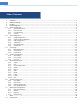
Table of Contents 1 2 3 4 Introduction ................................................................................................................................................................................................ 2 Web Access and Login ................................................................................................................................................................................. 3 Live View .................................................................
.2 Video Search .........................................................................................................................................................................30 5.2.1 Local Video Search ....................................................................................................................................................30 5.2.2 SD Card Video Search........................................................................................................................
1 Introduction Welcome Thank you for purchasing this network camera! Please read this manual carefully before operating the unit and retain it for further reference. Should you require any technical assistance, please contact Speco Technologies Technical Support at 1-800-645-5516.
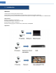
2 Web Access and Login The IP camera settings can be accessed via a web browser through the LAN. Access through IP Scanner Network connection: ① Make sure the PC and IP-Cam are connected on the same local network. The camera is set to DHCP by default and will be assigned an IP address by the DHCP server. Make sure that the local network has a DHCP server. Routers typically have a DHCP server built in. ② Install IP Scanner from the CD and run it after installation.
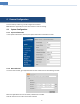
3 Live View The window below will be shown after logging in.
Click the zoom/focus control button to show the control panel.
4 Camera Configuration Press the “Setup” button to go to the configuration interface. Note: Wherever applicable, click the “Save” button to save the settings. 4.1 System Configuration 4.1.1 System Information In the “System Information” interface, the system information of the device is listed. 4.1.2 Date and Time To set the time and date, go to SystemDate and Time. Please refer to the following interface. Select the applicable time zone and enable / disable DST as needed.
4.1.3 Local Recording Go to SystemLocal Recording to set up the storage path of captured pictures and recorded videos on the local PC. There is also an option to enable or disable the bitrate display in the recorded files. For the model with built-in MIC, there is also an option to enable or disable audio recording. 4.1.4 Storage Go to SystemStorage to go to the interface as shown below. SD Card Management When the card is used for the first time, click the “Format” button to format the SD card.
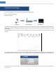
2. Set record stream, pre-record time and cycle writing. Pre Record Time: Set the time to record before the actual recording begins. 3. Set schedule recording. Check “Enable Schedule Record” and set the schedule. Weekly schedule Set the alarm time from Monday to Sunday for a single week. Each day is divided in one hour increments. Green means scheduled. Blank means unscheduled. “Add”: Add the schedule for a special day. Drag the mouse to set the time on the timeline. “Erase”: Delete the schedule.
Set the format, resolution and quality of the image saved on the SD card and the snapshot interval and quantity and the timing snapshot here. Snapshot Quantity: The number you set here is the maximum quantity of snapshots. The actual quantity of snapshots may be less than this number. Supposing the occurrence time of an alarm event is less than the time of capturing pictures, the actual quantity of snapshots is less than the set quantity of snapshots.
Saturation: Set the degree of color purity. The purer the color is, the brighter the image is. WDR: WDR can adjust the camera to provide a better image when there are both very bright and very dark areas simultaneously in the field of the view by lowering the brightness of the bright area and increasing the brightness of the dark area. Recording will be stopped for a few seconds while the mode is changing from non-WDR to WDR mode.
4.2.2 Video / Audio Configuration Go to ImageVideo / Audio interface as shown below. In this interface, set the resolution, frame rate, bitrate type, video quality and so on subject to the actual network condition. Click the “Audio” tab to go to the interface as shown below. Two video streams can be adjustable. Resolution: The size of image. Frame rate: The higher the frame rate, the video is smoother. Bitrate type: CBR and VBR are optional. Bitrate is related to image quality.
Set time stamp, device name, OSD content and picture overlap here. After enabling the corresponding display and entering the content, drag them to change their position. Then click the “Save” button to save the settings. 4.2.4 Video Mask Go to ImageVideo Mask interface as shown below. A maximum of 4 zones can be set up. To set up video mask: 1. Enable video mask. 2. Click the “Draw Area” button and then drag the mouse to draw the video mask area. 3. Click the “Save” button to save the settings. 4.
4.2.5 ROI Configuration Go to ImageROI Config interface as shown below. An area in the image can be set as a region of interest. This area will have a higher bitrate than the rest of the image, resulting in better image quality for the identified area. 1. Check “Enable” and then click the “Draw Area” button. 2. Drag the mouse to set the ROI area. 3. Set the level. 4. Click the “Save” button to save the settings. 4.2.6 Zoom/Focus This function is only available for the model with motorized zoom lens.
4.3 Event Setup 4.3.1 Motion Detection Go to Event Setup Motion Detection to set motion detection alarm. 1. Check “Enable” check box to activate motion based alarms. If unchecked, the camera will not send out any signals to trigger motion-based recording to the NVR or CMS, even if there is motion in the video. Trigger Snapshot: If selected, the system will capture images on motion detection and save the images on an SD card.
2. Click “Enable” and set the alarm holding time. 3. Set alarm trigger options. Trigger Email and FTP. The setup steps are the same as motion detection. Please refer to motion detection chapter for details. SD Card Error When there are some errors in writing to SD card, the corresponding alarms will be triggered. 1. Go to Event Setup AnomalySD Card Error as shown below. 2. Click “Enable” and set the alarm holding time. 3. Set alarm trigger options. Trigger Email and FTP.
4.4.1 Abnormality This function can detect changes in the surveillance environment affected by the external factors. Go to AnalyticsAbnormality interface as shown below. 1. Enable the applicable detection that’s desired. Video Blur Detection: Alarms will be triggered if the video becomes blurry. 2. Set the alarm holding time and alarm trigger options. The setup steps are the same as motion detection. Please refer to motion detection chapter for details. 3. Click “Save” button to save the settings. 4.
2. Set alarm trigger options. The setup steps are the same as motion detection. Please refer to motion detection chapter for details. 3. Click “Save” button to save the settings. 4. Set area and sensitivity of the line crossing alarm. Click the “Area and Sensitivity” tab to go to the interface as shown below. Set the alarm line number and direction. Up to 4 lines can be added. Multiple lines cannot be added simultaneously. Direction:A<->B, A->B and A<-B optional.
1. Enable region intrusion detection alarm and set the alarm holding time. 2. Set alarm trigger options. The setup steps are the same as motion detection. Please refer to motion detection chapter for details. 3. Click the “Save” button to save the settings. 4. Set the alarm area of the intrusion detection. Click the “Area” tab to go to the interface as shown below. Set the alarm area number on the right side. Up to 4 alarm areas can be added.
Use IP address (take IPv4 for example)-obtain a local IP address automatically through DHCP. A typical router has a DHCP server built in, and therefore is able to assign an IP address to the camera. Use PPPoE-Click the “PPPoE Config” tab to go to the interface as shown below. Enable PPPoE and then enter the user name and password from your ISP. Either method of network connection can be used. If PPPoE is used to connect internet, the camera will get a dynamic WAN IP address.
HTTP Port: The default HTTP port is 80. It can be changed to any port which is not occupied. HTTPS Port: The default HTTPs port is 443. It can be changed to any port which is not occupied. Data Port: The default data port is 9008. Please change it as necessary. RTSP Port: The default port is 554. Please change it as necessary. 4.5.3 Server Configuration This function is mainly used for connecting network video management system. 1. Check “Enable”. 2.
4.5.5 802.1x If it is enabled, the camera’s data can be protected. When the camera is connected to the network protected by the IEE802.1x, user authentication is needed. To use this function, the camera shall be connected to a switch supporting 802.1x protocol. The switch can be reckoned as an authentication system to identify the device in a local network. If the camera connected to the network interface of the switch has passed the authentication of the switch, it can be accessed via the local network.
Sub stream: The address format is “rtsp://IP address: rtsp port/profile2?transportmode=mcast”. Third stream: The address format is “rtsp://IP address: rtsp port/profile3?transportmode=mcast”. Audio: Having entered the main/sub stream in a media player(like VLC), the video and audio will play automatically. If “Allow anonymous login…” is checked, there is no need to enter the username and password to view the video.
4.5.9 HTTPS HTTPs provides authentication of the web site and protects user privacy. Go to NetworkHTTPS as shown below. There is a certificate installed by default as shown above. Enable this function and save it. Then the camera can be accessed by entering https://IP: https port via the web browser (eg. https://192.168.226.201:443). A private certificate can be created if users don’t want to use the default one. Click “Delete” to cancel the default certificate.
authority for signature. After receiving the signed certificate, import the certificate to the device. 4.5.10 QoS QoS (Quality of Service) function is used to provide different quality of services for different network applications. With the deficient bandwidth, the router or switch will sort the data streams and transfer them according to their priority to solve the network delay and network congestion by using this function. Go to NetworkQoS. Video/Audio DSCP: The range is from 0 to 63.
Modify user: 1. Select a user to modify password and MAC address if necessary in the user configuration list box. 2. The “Edit user” dialog box pops up by clicking the “Modify” button. 3. Enter the old password of the user in the “Old Password” text box. 4. Enter the new password in the “New password” and “Confirm Password” text box. 5. Enter computer’s MAC address as necessary. 6. Click the “OK” button to save the settings.
click the “Add” button. 4.6.4 Security Management Go to SecuritySecurity Management as shown below. In order to prevent against malicious password unlocking, “locking once illegal login” function can be enabled here. If this function is enabled, login failure after trying six times will make the login interface locked. The camera can be logged in again after a half hour or after the camera reboots. 4.7 Maintenance Configuration 4.7.1 Backup and Restore Go to MaintenanceBackup & Restore.
If necessary, the camera can be set up to reboot on a time interval. Enable “Time Settings”, set the date and time and then click the “Save” button to save the settings. 4.7.3 Upgrade Go to MaintenanceUpgrade. In this interface, the camera firmware can be updated. 1. Click the “Browse” button to select the save path of the upgrade file 2. Click the “Upgrade” button to start upgrading the firmware. 3.
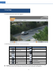
5 Search 5.1 Image Search In the Setup interface, click Search to go to the interface as shown below. Images that are saved on the PC or SD card can be found here. 1. 2. 3. 4. Local Image Search Choose “Picture”—“Local”. Set time: Select date and choose the start and end time. Click to search the images. Double click a file name in the list to view the captured photos as shown above.
Click to return to the previous interface. SD Card Image Search 1. Choose “Picture”—“SD Card”. 2. Set time: Select date and choose the start and end time. 3. Choose the alarm events at the bottom of the interface. 4. Click to search the images. 5. Double click a file name in the list to view the captured photos. Click to return to the previous interface. The descriptions of the buttons are shown as follows.
Icon Description Icon Description Close: Select an image and click this button to close the image. Close all: Click this button to close all images. Save: Click this button to select the path for saving the image on the PC. Save all: Click this button to select the path for saving all pictures on the PC. Fit size: Click to fit the image on the screen. Zoom in: Click this button to digitally zoom in. Slide show play: Click this button to start the slide show mode.
Icon Description Icon Description Play button. After pausing the video, click this button to continue playing. Pause button Stop button Speed down Speed up Watermark display Enable / disable audio; drag the slider to adjust the volume after enabling audio. (only some models support this function) 5.2.2 SD Card Video Search Click Search to go to the interface as shown below. Videos that were recorded on the SD card can be played in this interface. 1. Choose “Record”—“SD Card”. 2.
4. Select the alarm events at the bottom of the interface. 5. Select mix stream (video and audio stream) or video stream as needed. 6. Double click on a file name in the list to start playback. The time table can be shown in 24H/12H/2H/1H format by clicking the corresponding buttons. Video clip and downloading 1. Search the video files according to the above mentioned steps. 2. Select the start time by clicking on the time table. 3. Click to set the start time and then this button turns blue ( ). 4.
Click “Set up” to set the storage directory of the video files. Click “Open” to play the video. Click “Clear List” to clear the downloading list. Click “Close” to close the downloading window.
Appendix Appendix 1 Troubleshooting IP Scanner does not show any device. Make sure that the PC that’s running IP Scanner is on the same local network as the devices. Internet Explorer cannot download ActiveX control. IE browser may be set up to block ActiveX. Follow the steps below. 1. Open IE browser and then click ToolsInternet Options. 2. Select SecurityCustom Level. 3. Enable all the options under “ActiveX controls and plug-ins”. 4. Click OK to finish setup. No sound can be heard. 1.
Appendix 2 Specifications Specification /Model Image Sensor Image Size Electronic Shutter Iris Type Min. llumination Camera Image Lens Lens Mount Day&Night WDR Digital NR Angle Adjustment Video Compression H.
Specification /Model Image Sensor Image Size Electronic Shutter Iris Type Min. llumination Camera Image Lens Lens Mount Day&Night WDR Digital NR Angle Adjustment Video Compression H.
Specification /Model Image Sensor Image Size Electronic Shutter Iris Type Min. llumination Camera Image Lens Lens Mount Day&Night WDR Digital NR Angle Adjustment Video Compression H.
Specification /Model Image Sensor Image Size Electronic Shutter Iris Type Min. llumination Camera Image Lens Lens Mount Day&Night WDR Digital NR Angle Adjustment Video Compression H.