CPTZ32D5W 22X AIO PTZ Please read this manual thoroughly before use and keep it handy for future reference.
CAUTION EXPLANATION OF GRAPHICAL SYMBOLS The lightning flash with arrowhead symbol, within an equilateral triangle, is intended to alert the user to the presence of uninsulated “dangerous voltage” within the product’s enclosure that may be of sufficient magnitude to constitute a risk of electric shock to persons.
FCC COMPLIANCE STATEMENT FCC INFORMATION: This equipment has been tested and found to comply with the limits for a Class A digital device, pursuant to Part 15 of the FCC Rules. These limits are designed to provide reasonable protection against harmful interference when the equipment is operated in a commercial environment.
IMPORTANT SAFETY INSTRUCTIONS 1. 2. 3. 4. 5. 6. Read these instructions. Keep these instructions. Heed all warnings. Follow all instructions. Clean only with dry cloth. Do not block any ventilation openings. Install in accordance with the manufacturer’s instructions. 7. Do not install near any heat sources such as radiators, heat registers, stoves, or other apparatus (including amplifiers) that produce heat. 8. Do not defeat the safety purpose of the polarized or grounding-type plug.
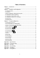
Table of Contents Chapter 1 — Introduction........................................................................................................... 1 1.1 Features .............................................................................................................................................1 Chapter 2 — Installation and Configuration ......................................................................... 2 2.1 Package Contents................................................................
Chapter 1 — Introduction 1.1 Features The dome camera and the keyboard controller make up the building blocks for any surveillance/security system. Using multiple keyboard controllers and multiple dome cameras, no place is too large for monitoring. Extensible and flexible architecture facilitates remote control functions for a variety of external switching devices such as multiplexers and DVRs.
Chapter 2 — Installation and Configuration 2.1 Package Contents The dome camera is designed with a compact, small size, hard dome camera housing. The housing is constructed of aluminum, steel and plastic. The housing is designed to be mounted on a wall or a ceiling. The housing meets the Protection Classification IP66 standards for dust and moisture resistance.
2.2 Installation You need one optional mount kit of the wall mount and the ceiling mount to install. The wall or ceiling mount must be attached to a structural object such as hard wood, concrete that will support the weight of the mount and dome camera. The use of a solid backboard is recommended when attaching to gypsum walls. 1. Remove the Protection pad and the tape from attached the dome camera. 2. Attach the mounting base to wall using the supplied M8 tapping screw and plastic bushing.
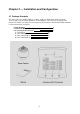
2.3 Basic Configuration of Dome Camera System Figure 1 – Basic Installation Diagram The dome camera must be installed by qualified service personnel in accordance with all local and federal electrical and building codes.
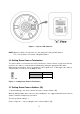
Figure 2 – Layout of DIP Switches NOTE: Open the switch cover (position “a”) and change the setting of DIP switches. The cover should be closed after setting DIP switches. 2.4 Setting Dome Camera Termination The device which is connected at end of line, whether it is a dome camera or keyboard controller, must have the cable for communication terminated by setting the appropriate DIP switch. Without proper termination, there is potential for control signal errors.
Example: Port 1 = Dome 1, Port 2 = Dome 2 … Port 16 = Dome 16. If more than 16 dome cameras are installed using two or more multiplexers, ID of the dome camera should be ID of MUX x No. of camera IN. (e.g.
DOME ID 36 37 38 39 40 41 42 43 44 45 46 47 48 49 50 51 52 53 54 55 56 57 58 59 60 61 62 63 64 65 66 67 68 69 70 71 72 73 74 75 76 77 78 79 80 D1 (1) OFF ON OFF ON OFF ON OFF ON OFF ON OFF ON OFF ON OFF ON OFF ON OFF ON OFF ON OFF ON OFF ON OFF ON OFF ON OFF ON OFF ON OFF ON OFF ON OFF ON OFF ON OFF ON OFF D2 (2) OFF OFF ON ON OFF OFF ON ON OFF OFF ON ON OFF OFF ON ON OFF OFF ON ON OFF OFF ON ON OFF OFF ON ON OFF OFF ON ON OFF OFF ON ON OFF OFF ON ON OFF OFF ON ON OFF D3 (4) ON ON ON ON OFF OFF OFF OFF O
DOME ID 81 82 83 84 85 86 87 88 89 90 91 92 93 94 95 96 97 98 99 100 101 102 103 104 105 106 107 108 109 110 111 112 113 114 115 116 117 118 119 120 121 122 123 124 125 D1 (1) ON OFF ON OFF ON OFF ON OFF ON OFF ON OFF ON OFF ON OFF ON OFF ON OFF ON OFF ON OFF ON OFF ON OFF ON OFF ON OFF ON OFF ON OFF ON OFF ON OFF ON OFF ON OFF ON D2 (2) OFF ON ON OFF OFF ON ON OFF OFF ON ON OFF OFF ON ON OFF OFF ON ON OFF OFF ON ON OFF OFF ON ON OFF OFF ON ON OFF OFF ON ON OFF OFF ON ON OFF OFF ON ON OFF OFF D3 (4) OFF
DOME ID 126 127 128 129 130 131 132 133 134 135 136 137 138 139 140 141 142 143 144 145 146 147 148 149 150 151 152 153 154 155 156 157 158 159 160 161 162 163 164 165 166 167 168 169 170 D1 (1) OFF ON OFF ON OFF ON OFF ON OFF ON OFF ON OFF ON OFF ON OFF ON OFF ON OFF ON OFF ON OFF ON OFF ON OFF ON OFF ON OFF ON OFF ON OFF ON OFF ON OFF ON OFF ON OFF D2 (2) ON ON OFF OFF ON ON OFF OFF ON ON OFF OFF ON ON OFF OFF ON ON OFF OFF ON ON OFF OFF ON ON OFF OFF ON ON OFF OFF ON ON OFF OFF ON ON OFF OFF ON ON OFF
DOME ID 171 172 173 174 175 176 177 178 179 180 181 182 183 184 185 186 187 188 189 190 191 192 193 194 195 196 197 198 199 200 201 202 203 204 205 206 207 208 209 210 211 212 213 214 215 D1 (1) ON OFF ON OFF ON OFF ON OFF ON OFF ON OFF ON OFF ON OFF ON OFF ON OFF ON OFF ON OFF ON OFF ON OFF ON OFF ON OFF ON OFF ON OFF ON OFF ON OFF ON OFF ON OFF ON D2 (2) ON OFF OFF ON ON OFF OFF ON ON OFF OFF ON ON OFF OFF ON ON OFF OFF ON ON OFF OFF ON ON OFF OFF ON ON OFF OFF ON ON OFF OFF ON ON OFF OFF ON ON OFF OFF
DOME ID 216 217 218 219 220 221 222 223 224 225 226 227 228 229 230 231 232 233 234 235 236 237 238 239 240 241 242 243 244 245 246 247 248 249 250 251 252 253 254 255 D1 (1) OFF ON OFF ON OFF ON OFF ON OFF ON OFF ON OFF ON OFF ON OFF ON OFF ON OFF ON OFF ON OFF ON OFF ON OFF ON OFF ON OFF ON OFF ON OFF ON OFF ON D2 (2) OFF OFF ON ON OFF OFF ON ON OFF OFF ON ON OFF OFF ON ON OFF OFF ON ON OFF OFF ON ON OFF OFF ON ON OFF OFF ON ON OFF OFF ON ON OFF OFF ON ON D3 (4) OFF OFF OFF OFF ON ON ON ON OFF OFF OFF
2.6 Setting Dome Camera Protocol and Video If a dome camera is to be installed with the keyboard controller, select the default protocol. Consult service personnel if a dome camera is installed with device other than a keyboard controller. S2 You can set video type with DIP switch. Select video type with D1 in S2. S2-D1 VIDEO TYPE OFF NTSC ON PAL You can set Protocol with DIP switch D2, D3 and D4 in S2.
• Connecting Alarms A1,A2,A3,A4 (Alarm Input 1,2,3,4) You can use external devices to signal the dome camera to react on events. Mechanical or electrical switches can be wired to the A1,A2,A3,A4 (Alarm Input 1,2,3,4) and G (Ground) connectors. See Chapter 3 — Program and Operation for configuring alarm input. G (Ground) NOTE: All the connectors marked G or GND are common. Connect the ground side of the alarm input and/or alarm output to the G (Ground) connector.
The dome can move the OSD position in the OSD position setup. (AREA TITLE) (FUNC TITLE ) (AF AE) (CTRL KEY TO MOVE) SAVE AND EXIT(ESC TO CANCEL) (ALARM MESSAGE) (DOME ID…) (ANGLE…) OSD Position Setup Chapter 3 — Program and Operation 3.1 Dome Camera Selection Before you program or operate a dome camera, you must select the dome camera by pressing No. + CAM keys. Example: Pressing 1 , 0 + CAM keys sequentially will select dome camera 10.
3.3 How to control the On-Screen Menu Utility Function Button MENU Call the On-screen menu utility. Joystick up or down Navigate through the menu items. Go into the sub-menu items. Joystick left or right or IRIS Open Change value. Enter the editing title mode. Joystick left or right or Zoom handle twist or Tele , Wide CTRL + Joystick Change value of angle. Enter the changing angle mode. IRIS Open Exit the changing angle mode. IRIS Close ESC Escape (EXIT) 3.
4. Twist the Joystick to change the alphanumeric characters and move the next position by pushing the Joystick to the left or right. Or move down to the character table and press the CTRL or IRIS Open key at the desired character then the cursor position moves to the next position automatically. Push the Joystick to the left or right at the “ALL DELETE” field to delete all characters. Push the Joystick to the left or right at the “EXIT” field to finish title edit menu.
Press the SCAN key on the angle field to display with the small OSD. Then the screen will show as below. AUTO SCAN AREA SETUP (CTRL KEY) NUMBER01 START : ----- ----END : ----- ----EXIT(ESC TO EXIT) The setting procedure is the same as above. NOTE: 09: AUTO-PAN mode (endless panning) 3.5 Preset (Shortcut: PRST) If you need to view specific places routinely, you should program Presets. A Preset is a programmed video scene with automatic pan, tilt, zoom, focus, motion and AE settings.
4. After aiming the camera (view direction and lens control), release the CTRL key. The cursor will be on the “TITLE” after saving data then twist the Joystick or press the Tele or Wide key to edit the Preset title. Follow the procedure of the Auto Scan above to edit titles. 5. Select “CAMERA SET” and push the Joystick to the left or right. Then the Preset camera setup displays.
The position, which is marked with the *, already has the Preset view assigned. Press the PRST key on the * to review the stored Preset. The camera will show the stored Preset scene. PRESET AREA SETUP (CTRL KEY) NUMBER 001 PAN TILT 000.0 000.0 EXIT(ESC TO EXIT) Hold down the CTRL key while selecting the desired scene using the Joystick. Current position will be displayed. Release the CTRL key to complete. Or Press the IRIS Open key then the “CTRL” displays. Move the desired position and the zoom position.
A04 P01 T02 : Auto Scan (1 ~ 8, 10 ~ 17) : Pattern (1 ~ 8) : Tour (1 ~ 8) Follow the steps below to program the Tours: 1. Press the MENU key to display the main menu on the monitor. Scroll to Tour and push the Joystick to the right to enter the Tour menu. Or just press the TOUR key on the keyboard. 2. Select “NUMBER” and set the desired number by pushing the Joystick to the left or right. 3. Choose a blank position to be programmed by pushing the Joystick up, down, right, or left. 4.
3.8 Pattern (Shortcut: PTRN) The Pattern feature records user control of the selected dome camera. Up to 8 Patterns can be stored and played back by pressing No. + PTRN keys subsequently. PATTERN SETUP (CTRL KEY) NO TITLE SEC PERCENT 01 : P01 000 00.0% 02 : P02 000 00.0% 03 : P03 000 00.0% 04 : P04 000 00.0% 05 : P04 000 00.0% 06 : P04 000 00.0% 07 : P04 000 00.0% 08 : P04 000 00.0% TOTAL 000 00.0% SAVE AND EXIT(ESC TO CANCEL) Follow steps below to program the Pattern: 1.
3.9 Alarm ALARM SETUP NO PRI FUN IN OUT 01 1 001 NO ON 02 1 --- OFF OFF 03 1 --- OFF OFF 04 1 --- OFF OFF DWELL : 03 ALARM OUT SETUP SAVE AND EXIT(ESC TO NO PRI(Priority) FUN(Function) IN OUT HLD(Hold) LATCH DWELL HLD LATCH 03 OFF 03 OFF 03 OFF 03 OFF CANCEL) : alarm input number : The lower number has higher priority. (0 ~ 4) : Stored function number to be called by alarm. : NO/NC – normally open/closed, OFF – ignore : ON – 5VTTL output, OFF – no output : Alarm will be held for programmed time.
TITLE SWAP : up to 12 characters. : Swap the start point for the end point. 1. Select “NUMBER” and set the desired number by pushing the Joystick to the left or right. 2. To edit the “TITLE”, follow the procedure of the Auto Scan above to edit titles. 3. Select “START ANGLE”. Hold down the CTRL key while selecting the start position using the Joystick. Current panning position will be displayed. Release the CTRL key to complete the selection of the start position.
3. Place the cursor at the “TITLE” field. Twist the Joystick to enter the title edit mode. Follow the procedure of the Auto Scan above to edit titles. 4. To turn the stored zone On or Off, twist the Joystick or press the Tele or Wide key. 5. Set the “METHOD”, “BLOCK” or “V.OFF(video off)”. 6. Select “SAVE AND EXIT” and push the Joystick to the right or press the IRIS Open key. Press the ESC or IRIS Close key to exit the program without saving.
FOCUS LIMIT This distance is approximate value and the focus operate from the setting value. CAUTION: Avoid continuous, 24-hour use of the auto focus. This will shorten the lifespan of the lens. • WB (White Balance) CONTROL WB SETUP MODE : AWB R GAIN : --B GAIN : --SAVE AND EXIT(ESC TO CANCEL) MODE AWB WAWB INDOOR OUTDOOR MANUAL RGAIN BGAIN AWB / WAWB / INDOOR / OUTDOOR / MANUAL Computes the white balance value output using color information from the entire screen automatically.
WDR WDR LEVEL NIGHT SHOT OFF / ON (NOTE: When ON, BACKLIGHT will be disabled.) LOW / MIDLOW / MID / MIDHIGH / HIGH AUTO / ON / OFF / GLOBAL NOTE: Values in ( ) are for PAL Camera. The WDR operates in AE1 mode only. NOTE: When BACKLIGHT set BLC or HLC, focus issues may occur in certain lighting conditions. The NIGHT SHOT option removes the IR cutoff filter of the camera and makes the camera sensitive to near infrared. AUTO GLOBAL Camera goes in to B&W mode at low light.
3.13 Dome Setup CONFIGURATION MENU LANGUAGE : ENGLISH HOME FUNCTION SETUP OSD DISPLAY VIEW ANGLE SETUP INITIALIZE DATA ORIGIN OFFSET DOME RESET SYSTEM MENU SYSTEM INFORMATION SAVE AND EXIT(ESC TO CANCEL) • LANGUAGE SETUP LANGUAGE : Select the desired language.
• OSD DISPLAY OSD DISPLAY SETUP CAMERA TITLE VIEW DIRECTION DOME OSD AREA TITLE PRESET TITLE FOCUS EXPOSURE OSD POSITION SETUP : : : : : : DOMEID OFF ON OFF CONSTANT ON SAVE AND EXIT(ESC TO CANCEL) CAMERA TITLE : up to 6 characters VIEW DIRECTION : ON / OFF “ON” sets current direction as N(North) and the coordinate angle to 000. “OFF” hides the directional title. Every 90 degrees of clockwise rotation will change the title to E(East), S(South) or W(West).
• VIEW ANGLE SETUP VIEW ANGLE SETUP PANNING RANGE FLIP : 90 TILT LIMIT : OFF SAVE AND EXIT(ESC TO CANCEL) FLIP: OFF, AUTO, 90 , 100 , 110 , 120 , OFF: The dome camera moves until 90 vertically. AUTO: When the camera reaches the floor directly above the moving object, it will stop. At that time, release the Joystick instantly and pull it down again to run the auto-flip function. When you use the panning range, it is recommended to use the flip mode to AUTO.
• INITIALIZE DATA INITIALIZE DATA FACTORY DEFAULT ERASE PROGRAMMED DATA PRESET FOCUS DEFAULT EXIT(ESC TO EXIT) FACTORY DEFAULT Select “FACTORY DEFAULT” to initialize the data. FACTORY DEFAULT ARE YOU SURE ? CANCEL OK ERASE PROGRAMMED DATA Erase all stored data from the Flash-ROM of the selected dome camera. You will be asked to enter ON or OFF. If you desire to erase all data then select “ERASE” run, otherwise press the ESC key to exit without erasing.
• ORIGIN OFFSET OFFSET SETUP (CTRL KEY) PAN OFFSET : TILT OFFSET : ENABLE : SAVE AND EXIT(ESC TO 000.0 000.0 OFF CANCEL) This feature is useful to align a new dome camera exactly the same as the previously installed dome camera. Dome camera’s origin set and all data initialize option do not override offset values. Only the default set option in this menu will set the offset value to zero. This can be used to avoid ceiling obstructions.
MOTOR SETUP Motor Setup menu provides the pan and tilt speed of a camera. User can set the desired speed with pushing the Joystick to the left or right. During operation, pressing 153 + ON keys will change the speed to the SLOW mode and pressing 153 + OFF keys will change the speed to the Normal mode. Press and hold the CTRL key and moving the Joystick will operate with the TURBO speed mode.
WHITE DEFECT COMPENSATION White defect of CCD sensor will be compensated. WHITE DEFECT COMPENSATION ARE YOU SURE ? CANCEL OK • SYSTEM INFORMATION SYSTEM INFORMATION CAMERA TYPE H/W VERSION ROM VERSION PROTOCOL BAUDRATE : : : : : xxxxx-Vx.xxxx Vx.xx-xxxx Vx.xxxxx xxxx 9600 EXIT(ESC TO EXIT) The system information provides essential information about the dome camera if service is required. This screen displays the camera type and ROM version. The information on this screen cannot be modified. 3.
- HOME Select “HOME” and press the CTRL key. The dome camera goes to the default position that it returns to after an assigned period of inactivity passes. The default position may be a Preset, Tour, Pattern or no action. - AUTO PAN You can execute the endless auto pan to turn in one direction continuously by selecting Auto Pan. - ALARM OUT This function can operate only when the alarm out setup has the time in the alarm menu.
Appendix A — Specifications 22X AIO PTZ CAMERA MODEL CPTZ32D5W MODULE CCD Type Optical / Digital Zoom Max Resolution Focal Length 1/4" Type Super HAD CCD II 22X / 16X 700 TVL f = 3.9mm ~ 85.8mm 3.9mm – 49.5° (H) 85.8mm – 2.4° (H) F1.6 ~ F3.7 Angle of View F-Number Min.
Figure 6 – Dimension 36
Appendix B — Troubleshooting If problems occur, verify the installation of the camera with the instructions in this manual and with other operating equipment. Isolate the problem to the specific piece of equipment in the system and refer to the equipment manual for further information. Problem Possible Solution No video. Verify that power is connected to all pieces of equipment in the system. Verify that the power switches are in the ON position. Check the video connections. Poor video quality.
On-screen Menu The text overlay menu system used for setting dome features. The utility is accessed using a keystroke combination. The utility provides settings for camera functions, zoom, alarm, text display, and password protection. Flip Allows the dome to automatically turn 180 degrees when the camera tilts to its lower limit and stays in that position for a brief delay. When the dome flips (rotates), the camera starts moving upward as long as the tilt control is kept in the down position.
Slow Shutter Setting used to improve the quality of video obtained in extreme low-light situations. When the Slow Shutter setting is enabled, low-light information is collected over multiple fields based on the Shutter Limit setting. As a result, video may appear blurred or choppy in extreme low-light situations. This setting does not effect camera operation in normal lighting situations. Pattern A series of pan, tilt, zoom and focus movements from a single programmable dome.
Appendix D — Short Cut Key Short Cut Key Function PRST Pop up Preset setup menu TOUR Pop up Tour setup menu PTRN Pop up Pattern setup menu SCAN Pop up Auto Scan setup menu No.
Appendix E — Wall Mount The wall mounting plate must be attached to a structural object such as concrete that will support the weight of the mount and Dome Camera. 1. Select a suitable mounting location and verify there is sufficient cable to reach the middle of the Wall Mount. 2. Mark and drill mounting holes in the surface using the Wall Mount Flange. 3. Pull out cables required to connect to the dome camera from the wall or route cables through a section of 0.75 in. (19 mm) conduit pipe. 4.
Appendix F — Ceiling Mount The ceiling mounting plate must be attached to a structural object such as concrete that will support the weight of the mount and Dome Camera. 1. Select a suitable mounting location and verify there is sufficient cable to connect with cables from the housing. 2. Mark and drill mounting holes in the surface using the ceiling mount flange. 3. Pull out cables required to connect to the dome camera from the ceiling. 4.
CPTZ32D5W 22X Pan Tilt Zoom Camera Printed in Korea 50303339A