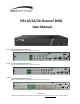
HRL (6/16/24 Channel DVR) User Manual H6HRL 6 Channel Hybrid Digital Video Recorder 4 Configurable Hybrid Channels (TVI or IP) plus 2 IP Channels H16HRL 16 Channel Hybrid Digital Video Recorder 8 Configurable Hybrid Channels (TVI or IP) plus 8 IP Channels H24HRL 24 Channel Hybrid Digital Video Recorder 8 Configurable Hybrid Channels (TVI or IP) plus 8 IP Channels, plus 8 TVI Channels Version 1.0 Features and specifications are subject to change, please check www.specotech.com for firmware updates.
DVR User Manual Notes& Contents Notes Please read this user manual carefully to ensure that you can use the device correctly and safely. The contents of this manual are subject to change without notice. Do not install this device near any heat sources such as radiators, heat registers, stoves or other devices that produce heat. Do not install this device near water. Clean only with a dry cloth. Do not block any ventilation openings and ensure proper ventilation around the machine.
DVR User Manual Notes& Contents Contents 1 Introduction...............................................................................................................................................................................................1 1.1 Welcome ........................................................................................................................................................................................................... 1 1.2 Features ..............................
Notes& Contents DVR User Manual 5.3.2 Image Settings ...................................................................................................................................................................................... 25 5.3.3 Mask Settings ....................................................................................................................................................................................... 25 5.3.4 Water Mark Settings ......................................
Notes& Contents DVR User Manual 8.4.6 View Export Status ............................................................................................................................................................................... 52 9 Alarm Management ................................................................................................................................................................................. 53 9.1 Sensor Alarm ........................................................
Notes& Contents 11 DVR User Manual Device Management ................................................................................................................................................................................ 70 11.1 Network Configuration .................................................................................................................................................................................. 70 11.1.1 TCP/IP Configuration .......................................
DVR User Manual Introduction 1 Introduction 1.1 Welcome Thank you for purchasing this DVR. If technical assistance is needed, please contact Speco Technologies Technical Support. Phone: Email: 1-800-645-5516 option 3 techsupport@specotech.com 1.2 Features Basic Functions Supports network device access including IP camera/dome and the Onvif IP cameras The DVR supports the H.265 and H.
DVR User Manual Introduction Supports any area of the image to be zoomed in to a maximum of 16 times of the current size Supports image and lens adjustment (only available for some cameras) Supports quick camera adding in the camera window of the live view interface Disk Management H16HRL/H24HRL supports 2 SATA HDDs H16HRL supports 1 SATA HDD Supports 1 e-SATA HDD Each SATA interface of the DVR supports the HDDs with max 14TB storage capacity Supports disk group configuratio
DVR User Manual Introduction Alarm Management Supports alarm schedule setting Supports enabling or disabling of the motion detection, external sensor alarm input, intelligence alarm and exception alarms including IP address conflict alarm, disk IO error alarm, disk full alarm, no disk alarm, illegal access alarm, network disconnection alarm, IPC offline alarm and so on, alarm trigger configuration supportable Supports IPC offline alarm trigger configuration of PTZ, snapshot, pop-up video, etc.
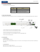
DVR User Manual Introduction 1.3 Front Panel Descriptions The following descriptions are for reference only. Name Descriptions REC When recording, the light is blue Net When access to network, the light is blue Power Power indicator, when connection, the light is blue 1.4 Rear Panel Descriptions To quickly get started, connect the following to your recorder in the following order, please refer to the following figure (H24HRL shown for reference). 1.
DVR User Manual Basic Operation Guide 2 Basic Operation Guide 2.1 Startup & Shutdown Please make sure all the connections are done properly before you power on the unit. Proper startup and shutdown are crucial to extending the life of your device. 2.1.1 Startup ① Connect the output display device to the VGA/HDMI interface of the DVR. ② Connect with the mouse and power. The device will boot and the power LED would turn blue.
DVR User Manual Basic Operation Guide Button Function Power Button Switch off—to stop the device Record Button To start recording -/-- /0-9 Input number or choose camera Fn1 Button Unavailable temporarily Multi Button To choose multi screen display mode Next Button To switch the live image SEQ To go to sequence view mode Audio To enable audio output in live mode Switch No function temporarily Direction button To move cursor in setup or pan/title PTZ Enter Button To confirm the choic
DVR User Manual Basic Operation Guide The system includes two input boxes. Refer to the above pictures. The left box is the number input box and the right box is the input box which provides inputs of numbers, letters and punctuation characters. The introductions of keys on the input boxes are shown below. Button Meaning Button Meaning Backspace key Switch key of punctuation character Delete Key Enter key Switch key between upper and lower letter Space key Switch key of language 2.
DVR User Manual EZ Setup & Main Interface 3 EZ Setup & Main Interface 3.1 EZ Setup The disk icons will be shown on the top of the startup interface. You can view the number and status of each disk quickly and conveniently through these icons ( : no disk; : unavailable disk; : RW available disk). You must configure the wizard if you start the DVR for the first time (or click “Skip” to cancel the EZ Setup next time). The first time you start up your DVR, you shall choose the language and locality as needed.
DVR User Manual EZ Setup & Main Interface Enable pattern lock and click “Edit” to set the pattern lock. Click “Edit Security Question” to set questions and answers for password security of admin. If you forget the password, please refer to Q4 in Appendix A FAQ for details. Click “Next” to continue. After you log in, you will see an EZ setup interface as shown below. Click “OK” to start wizard. The EZ Setup steps are as follows. ① System Login.
DVR User Manual EZ Setup & Main Interface Click “Next” to continue or click “Cancel” to exit the wizard. ② Network Settings. Select the network work pattern as required. Check “Obtain an IP address automatically” and “Obtain DNS automatically” to get the IP address and DNS automatically (the DHCP function of the router in the same LAN should also be enabled), or manually enter them. Enter the HTTP port, RTSP port and Server port (please see 12.1.2 Port Configuration for details).
DVR User Manual EZ Setup & Main Interface ④ Add Camera. To add cameras from the LAN, make sure all cameras are set to DHCP. Click “Refresh” to refresh the list of online IP cameras which are in the same local network with DVR and then click to add the searched camera. Click “Add All” to add all the cameras in the list. Click to delete the added camera. Click “Delete All” to delete all the added cameras. Click to edit the searched IP camera as shown on the below left.
DVR User Manual EZ Setup & Main Interface the camera. You can click “Test” to test the effectiveness of the input information. Click “OK” to save the settings. You can change the IP camera name only when the added camera is online. Click “Next” to continue. ⑤ Disk Settings. You can view the disk number, disk capacity of the DVR and serial number, R&W status of the disk. Click “Formatting” to format the disk. Click “Next” to continue. ⑥ Record Settings. Two record modes are available: auto and manual.
DVR User Manual EZ Setup & Main Interface The buttons in area ① are introduced in the table below. Button Meaning Start button. Click it to pop up area ③. Full screen button. Click it to show full screen; click it again to exit the full screen. Screen mode button. Sequence button (see 5.2.2 Quick Sequence View and 5.2.4 Scheme View in Sequence for details). Click it to enable OSD; click again to disable OSD. Click to set the default playback time before starting instant playback (8.
DVR User Manual EZ Setup & Main Interface one camera in the list to preview the camera image in the selected window. Click “Customize Layout” to view all the display modes in the display mode list (refer to 5.2.1 Display Mode for detail configuration of the display mode). Double click one display mode in the list to switch to the display mode for previewing. Introduction of area ③: Icon / Button Meaning It shows the current login user. Click to go to record search and export interface, see 8.
DVR User Manual EZ Setup & Main Interface Here we take Camera module as an example. The Camera module provides convenient links such as “Add Camera”, “Edit Camera”, “Image Settings”, “Motion”, “Intelligence Analytics” and “PTZ”. Click Camera to go to the camera management interface as shown below. There are some function items on the left side of the camera management interface. Click each item to go to corresponding interface or window.
DVR User Manual EZ Setup & Main Interface Alarm The module covers the functions such as Sensor and Motion Alarm Handling and Alarm Out Settings. Please see Chapter 9 Alarm Management for details. Disk The module covers the functions such as Disk Management, Storage Mode and Disk Information and so on. Please see Chapter 7 Record & Disk Management for details. Network The module covers the functions such as TCP/IP, DDNS, Port, E-mail and Network Status and so on. Please see 11.
DVR User Manual Live View Introduction 4 Camera Management 4.1 Camera Signal Click StartSettingsCameraManage CameraCamera Signal to go to the interface as shown below. Some models may support analog signal switching to IP signal, which means decreasing (or increasing) the number of analog channels will accordingly increase (or decrease) the number of IP channels. The DVR device supports hybrid access of TVI, and CVBS high definition cameras.
DVR User Manual Live View Introduction Quickly Add Check the cameras and then click “Add” to add cameras. Click to edit the camera’s IP address, username and password and so on. Click “Default Password” to set the default username and password of each camera.
DVR User Manual Live View Introduction header line and then click “Modify IPC Password” to pop up a window (check the IPCs in the window, set the new password and then click “OK” button; only the online IPCs’ passwords can be modified and a batch of IPCs’ passwords can be modified at the same time).
DVR User Manual Live View Introduction 5 Live View Introduction 5.1 Live View Interface Introduction Refer to the interface as shown below, drag one camera in the preview window to another window for camera window exchanging.
DVR User Manual Live View Introduction image. Click the camera selection box to select other cameras for amplification. Click “Back” to return to the live view interface. 5.2 View Mode 5.2.1 Display Mode Set different screen modes and cameras’ display sequences as needed and then save the display modes classified by surveillance areas, priorities and so on. Refer to the picture below. Double click one display mode in the display mode list to view the live images in this mode.
DVR User Manual Live View Introduction ③ Click under the display mode list and then enter the display mode name in the popup window, click the “OK” button to save the current display mode. Method Two: ① Click StartSettingsSystemBasicOutput Settings to go to the interface and then set the screen mode. ② Double click the camera or camera group in the list to add them to the selected window. ③ Click to save the current display mode (refer to 5.2.4 Scheme View In Sequence for detail configurations).
DVR User Manual Live View Introduction 5.2.3 Scheme View In Sequence Click StartSettingsSystemBasicOutput Settings to go to the interface as shown below.
DVR User Manual Live View Introduction Click on the left to create a new scheme. Each scheme can only add one analog camera. Select a scheme on the left and then double click or drag a camera on the right to the scheme window in the middle of the interface. After finishing the settings of all the schemes, select the sequence interval and click “Apply” to start playing the schemes in sequence in output 2. 5.3 Image Configuration 5.3.
DVR User Manual Live View Introduction 5.3.2 Image Settings Click StartSettingsCameraImageImage Settings to go to the following interface. Select the camera and then set the brightness, contrast, saturation and hue of the camera. Click “Advanced” button or in the camera list on the right side of the interface to pop up “Image Adjust” interface and then set the relevant setting items. Please refer to 5.4.5 Image Adjustment for detailed introductions of these items.
DVR User Manual Live View Introduction 5.3.5 Image Adjustment Go to the live view interface and then click button on the tool bar under the camera window to go to the image adjustment interface. Image Adjustment Select the camera and then click “Image Adjustment” to go to image adjustment tab. Refer to the above picture. Drag the slider to set the camera’s brightness, contrast, saturation and hue value. Check sharpen, wide dynamic and denoise and then drag the slider to set the value.
DVR User Manual Live View Introduction Parameter Sharpen Meaning It relates to the resolution level of the image plane and the sharpness level of the image edge. The wide dynamic range (WDR) function helps the camera provide clear images even under Wide Dynamic back light circumstances. When there are both very bright and very dark areas simultaneously in the field of view, WDR balances the brightness level of the whole image and provide clear images with details.
DVR User Manual Live View Introduction Button/Parameter Meaning Day/night mode If checked, the lens will focus automatically when the camera is switching day/night switch autofocus mode. Time Interval It is the time interval when camera lens is auto-focusing. The interval can be set in the drop-down list. Note: if the lens of the camera connected to the DVR is fixed, the lens control function is unavailable.
DVR User Manual PTZ 6 PTZ 6.1 PTZ Control Interface Introduction You can control the IP dome or PTZ which connects to the IP camera for PTZ control. Click on the tool bar at the bottom of the live view window to go to the PTZ control interface as shown below. You can select another IP dome or PTZ which connects to the IP camera on the top right of the interface for PTZ control. Introductions of the buttons on the bottom right of the interface: Button Meaning Click / / / to rotate the dome.
DVR User Manual PTZ farther you drag the analog joystick from the middle of the image, the faster the dome or PTZ rotates. The dome or PTZ will stop rotating when you stop dragging the analog joystick. 3D Control Click the camera image on any area and then the image will be centered on the clicked point. Refer to the picture as shown below. Drag the mouse from A to B to get a green rectangle and the rectangle area will be zoomed in. Refer to the picture as shown below.
DVR User Manual PTZ Press and hold the left button of the mouse on any area of the camera image to zoom in the image; press and hold the right button to zoom out the image. Move the cursor of the mouse to the camera image and then slide the scroll wheel of the mouse forward to zoom in the image, slide the scroll wheel of the mouse backward to zoom out the image. OSD Setting Go to PTZ protocol setting interface and then set the protocol before you bring up the OSD.
DVR User Manual PTZ You can also go to preset setting interface for preset setting, see 6.2 Preset Setting for details. Cruise Setting Click “Cruise” to go to cruise operation tab and then click “Add” button to pop up a window as shown below left. You can add 8 cruises for each dome at most. ① Enter the cruise name in the “Add Cruise” window and then click “Add preset” to pop up the “Add Preset” window (Before adding preset to the cruise, please add preset of the dome first).
DVR User Manual PTZ Add preset Select camera and then click “Add” button to add preset; or click in the camera list on the right side of the interface to display the preset information of the dome and then click to add preset. The operations of the “Add Preset” window are similar to that of the PTZ control interface; please see 6.1 PTZ Control Interface Introduction for details. Edit preset Select camera and preset.
DVR User Manual PTZ Add Cruise Click in the camera list on the right side of the interface to display the cruise information of the dome and then click to add cruise. The operations of the “Add Cruise” window is similar to that of the PTZ control interface; please see 6.1 PTZ Control Interface Introduction for details. Edit Cruise Select the camera and cruise in the “Cruise” interface. Enter the new cruise name and then click to save the cruise name.
DVR User Manual Record & Disk Management 7 Record& Disk Management 7.1 Record Configuration 7.1.1 Mode Configuration Please format the HDDs before recording (refer to 7.5 Disk Management for details). Click StartSettingsRecordMode Settings to go to the mode settings interface. You can set the record time under the “Manual Record Settings” and then click “Apply” to save the settings. There are two record modes: auto mode and manual mode.
DVR User Manual Record & Disk Management Select one auto mode to pop up the corresponding window. Set the encode, GOP, resolution, FPS, bitrate type, quality, max bitrate and audio of each camera and then click “OK” to save the settings. Please adjust the parameters according to the actual condition. Video Encode: the available options will be H.265 and H.264 if the connected IP camera supports H.265, or the option will be H.264 only. GOP: group of pictures.
DVR User Manual Record & Disk Management Pre-alarm Record Time: set the time to record before the actual recording begins. Post-alarm Record Time: set the time to record after the actual recording is finished. Expiration Time: set the expiration time for recorded video. If the set date is overdue, the recorded data will be deleted automatically. 7.2 Encode Parameters Setting Click StartSettingsRecordEncode Parameters to go to the interface as shown below.
DVR User Manual Record & Disk Management 7.3 Schedule Setting 7.3.1 Add Schedule Click StartSettingsRecordRecord ScheduleEdit Schedules to go to the interface as shown below. “24×7”, “24×5” and “24×2” are the default schedules; you cannot edit or delete “24×7” while “24×5” and “24×2” can be edited and deleted. Click the schedule name to display the detailed schedule information on the left side of the interface.
DVR User Manual Record & Disk Management Set the schedule name and schedule time and then click “Add” to save the schedule. You can set day schedule or week schedule. : add button; : delete button. Set Day Schedule Click and then drag the cursor on the time scale to set record time; click selected area. and then drag the cursor on the time scale to delete the You can manually set the record start time and end time. Click or and then click “Manual” on each day to pop up a window as shown below.
DVR User Manual Record & Disk Management Set Week Schedule Click or and then click “Manual” beside to set the week schedule. Refer to the picture below. Set the start and end time, check the days in the window and then click “OK” to save the settings. Click “All” to set all week recording; click “Reverse” to swap the selected and unselected time in a week; click “Clear All” to clear all the selected area in a week. 7.3.
DVR User Manual Record & Disk Management Set the timing record schedule of each camera. See 7.3 Schedule Setting for details. 7.4.3 Motion Based Recording Motion Based Recording: the system will start motion based recording when the motion object appears in the setup schedule. The setup steps are as follows: ① Set the motion based recording schedule of each camera. See 7.3 Schedule Settingfor details. ② Enable the motion and set the motion area of each camera. See 9.2.1 Motion Configuration for details.
DVR User Manual Record & Disk Management There are four disk groups. By using disk group, you can correspond the camera to disk (the record data of the camera in the group will be stored into the disks in the same group). The DVR with e-SATA interface supports e-SATA recording. The added disks and cameras will be added into group one automatically.
DVR User Manual Alarm Management 8 Playback& Backup 8.1 Instant Playback Click on the tool bar at the bottom of the preview camera window to play back the recorded video (click on the tool bar at the bottom of the live view interface to set the default playback time). Refer to the picture below. Drag the playback progress bar to change the playback time. You can also click the right-click menu “Instant Playback” in the camera window and then set the instant playback time to play back the record. 8.
DVR User Manual Alarm Management the playback window to pop up the “Add Camera” window. Check the cameras in the window and then click “Add” to add playback camera. The system supports a maximum of 16 synchronous playback cameras. The buttons on the tool bar (area ①) at the bottom of the playback interface are introduced in the table below. Button Meaning Start button. Click it to pop up area ②. Full screen button. Click it to show full screen; click it again to exit the full screen.
DVR User Manual Alarm Management Button Meaning Click it to Go to the live view interface; see Chapter 5 Live View Introduction for details. Click on the playback window to show the tool bar as shown in area ③; right click on the window to show the menu list. The tool bar and menu list are introduced in the table below. Button Menu List Meaning -- Move tool. Click it to move the tool bar anywhere. Enable Audio Click it to enable audio. You can listen to the camera audio by enabling audio.
DVR User Manual Alarm Management 8.3 Smart Playback Smart Playback Settings Click to go to the following interface. Set the value of “Speed of non-interest video” (Please skip this one if you click “Skip non-interest video”), “Speed of interest video” and “Intrusion percentage”. Smart Playback by Drawing Rectangle Click and draw a rectangle in the desired area. Then the system will automatically search the record files of this area.
DVR User Manual Alarm Management Smart Playback by Drawing Quadrilateral Click and draw a quadrangle in the desired area. Then the system will automatically search the record files of this area. The cyan blocks indicate that there are intelligent recording files. Move the cursor to such block and click to play the record. 8.4 Record Search, Playback &Export The record data and the captured pictures can be exported through network, USB (U disk or USB mobile HDD).
DVR User Manual Alarm Management ② Select one camera in the interface and then click “Open” button. ③ Click the image box to play the record in the small playback box on the left side of the interface (the box which has image inside indicates that the record data exist). ④ Refer to the picture below. Drag the color blocks on the time scale to select the record data and then click “Export” button to pop up the “Record Backup” window as shown below.
DVR User Manual Alarm Management Time Slice Search: Method One: Click “Year”, “Month” or “Day” button under the record time scale to select the time slice mode. In “Day” mode, click / on the left/right side of the time scale to view the record of the last/next day; click “Minute” in the “Picture” option under the time scale to select “Minute” mode (in “Minute” mode, click the time scale to change the time of the 60 display windows) and click “Hour” to select “Hour” mode.
DVR User Manual Alarm Management 8.4.3 Event Search ① Click StartSearch and ExportEvent Search to go to “Event Search” tab as shown below. ② Check the event type in the interface as required. ③ Click to set the start time and end time on the top left of the interface. ④ Check cameras on the left side of the interface or check “All” to select all the cameras and then click searched record will be displayed in the list. ⑤ Click in the list to play back the record in the popup window.
DVR User Manual Alarm Management 8.4.4 Bookmark Search Only if you add the tags can you play the record by tag search. Click StartPlayback to go to the playback interface and then click bottom of the camera window to add bookmarks when you want to mark the playback time point of the selected camera. on the Click StartSearch and ExportBookmarks to go to “Bookmarks” tab. Click in the interface to play the record. Click to edit the tag name. Click to delete the tag. 8.4.
DVR User Manual Alarm Management 8.4.6 View Export Status Click StartSearch and ExportExport Status or click on the tool bar at the bottom of the playback interface to view the export status.
DVR User Manual Alarm Management 9 Alarm Management 9.1 Sensor Alarm To complete the entire sensor alarm settings, you should enable the sensor alarm of each camera and then set up the alarm handling of each camera. ① Click StartSettingsAlarmSensor Alarm to go to the following interface. ② Select schedule and the alarm type (NO or NC) according to trigger type of the sensor. ③ Enable the sensor alarm of each camera.
DVR User Manual Alarm Management Pop-up Video: After camera setting, the system will pop up the corresponding video automatically when the sensor alarm is triggered. To set the duration time of the video, please see 9.5.3 Display for details. Pop-up Message Box: if enabled, the system will pop up the corresponding alarm message box automatically when the sensor alarm is triggered. To set the duration time of the message box, please see 9.5.3 Display for details.
DVR User Manual Alarm Management ② Enable or disable “Record”, “Snapshot”, “Push”, “Alarm-out”, “Preset”, “Buzzer”, “Pop-up Video” and “E-mail”. The alarm handling settings of motion alarm the same as the sensor alarm (see 9.1 Sensor Alarm for details). ③ Click “Apply” to save the settings. You can click “Motion Settings” to go to the motion configuration interface. 9.3 Smart Event 9.3.
DVR User Manual Alarm Management ② Enable or disable “Snapshot”, “Push”, “Alarm-out”, “Preset”, “Buzzer”, “Pop-up Video” and “E-mail”. The alarm handling setting of object detection alarm is similar to that of the sensor alarm (see 9.1 Sensor Alarm for details). ③ Click “Apply” to save the settings. You can click “Object Config” to go to the object detection configuration interface. 9.3.
DVR User Manual Alarm Management ② Enable or disable “Snapshot”, “Push”, “Alarm-out”, “Preset”, “Buzzer”, “Pop-up Video” and “E-mail”. The alarm handling setting of exception detection alarm is similar to that of the sensor alarm (see 9.1 Sensor Alarm for details). ③ Click “Apply” to save the settings. You can click “Exception Config” to go to the exception detection configuration interface. 9.3.
DVR User Manual Alarm Management ② Enable or disable “Snapshot”, “Push”, “Alarm-out”, “Preset”, “Buzzer”, “Pop-up Video” and “E-mail”. The alarm handling setting of line crossing alarm is similar to that of the sensor alarm (see 9.1 Sensor Alarm for details). ③ Click “Apply” to save the settings. You can click “Crossing Config” to go to the line crossing configuration interface. 9.3.
DVR User Manual Alarm Management ⑥ Click “Processing Mode” to go to the alarm handling configuration interface of intrusion detection. Intrusion Detection Alarm Handling Configuration: ① Click StartSettingsAlarmIntelligence AlarmIntrusion to go to the following interface. ② Enable or disable “Snapshot”, “Push”, “Alarm-out”, “Preset”, “Buzzer”, “Pop-up Video” and “E-mail”. The alarm handling setting of intrusion detection alarm is similar to that of the sensor alarm (see 9.
DVR User Manual Alarm Management ② Enable or disable “Record”, “Snapshot”, “Push”, “Alarm-out”, “Preset”, “Buzzer”, “Pop-up Video”, “Pop-up Message Box” and “E-mail”. The Video Loss Settings are similar to that of the sensor alarm (see9.1 Sensor Alarmfordetails). ③ Click “Apply” to save the settings. 9.4.3 Warning Handling Settings ① Click StartSettingsAlarmExceptionWarning Handling Settings to go to the interface as shown below.
DVR User Manual Alarm Management ② Set the delay time and the schedule of each alarm-out. You can click “Edit Schedules” to edit the schedules (see 7.3.1 Add Schedule for details). ③ Click “Apply” to save the settings. You can click “Test” to test the alarm output. 9.5.2 E-mail Click StartSettingsAlarmEvent NotificationE-mail to go to the e-mail configuration interface. Set the e-mail address of the recipients. See 11.1.5 E-mail Configuration for details. 9.5.
DVR User Manual Alarm Management 9.5.5 Push Message Click StartSettingsAlarmEvent NotificationPush Message to go to the interface as shown below. Check “Enable” and then click “Apply” button to save the settings. If Push Server is online, it will push messages to the mobile clients. 9.5.6 Alarm Server Go to AlarmAlarm Server interface as shown below. Enable the alarm server and enter server address and port of the alarm server. Then select protocol.
DVR User Manual Alarm Management Click “Clear” button to stop the buzzer when the buzzer alarm happens. Click to view the detail information as shown below. If the exception information is more than one page, you can enter the number in the box and then click to jump to the specified page. Click / to view the exception alarm information in the previous/next page. Click to play the alarm record.
DVR User Manual Account & Permission Management 10 Account & Permission Management 10.1 Account Management Click StartSettingsAccount and AuthorityAccountEdit User to go to the interface as shown below. Area ① displays the user permissions. Area ② displays the user list. Click the user in the list to display its user permissions in area ①. There are three default permission groups (“Administrator”, “Advanced” and “Common”) available when adding accounts.
DVR User Manual Account & Permission Management ② Set the username, password and group. User can also set the pattern lock here. The e-mail address is optional. Click “Add” to add the user. 10.1.2 Edit User Click StartSettingsAccount and AuthorityAccountEdit User and then click information. Click to delete the user (the user admin cannot be deleted). in the user list or double click the user to edit the user Edit Security Question You can set password security only for admin.
DVR User Manual Account & Permission Management Enter current password and then check “Enable” to input pattern lock. Recover Password Click “Recover Password” to reset the password. Edit User Click “Edit User” to pop up the window as shown below. The admin is enabled, its permission control is closed and permission group cannot be changed by default.
DVR User Manual Account & Permission Management 10.3 Permission Management 10.3.1 Add Permission Group Click StartSettingsAccount and AuthorityAccountEdit Permission Group to go to the interface as shown below. Click to add permission group. Set the group name, check the permissions as needed and then set the “Local” and “Remote” permissions. Click “Add” to save the settings. 10.3.
DVR User Manual Account & Permission Management 10.4 Block and Allow List ① Click StartSettingsAccount and AuthoritySecurity to go to the following interface. ② Check “Enable” and then choose “Enable Allow List” or “Enable Block List” (the PC client of which the IP address is in the allow list can access DVR remotely while the PC client in the block list cannot). ③ Add IP/IP segment/MAC.
DVR User Manual Account & Permission Management In this interface, you can set the level and expiration time of the password. 10.7 View Online User Click StartSettingsAccount and AuthorityUser Status to view the online user information (you can view the online user name, login type, IP address and login time; click to pop up a window showing the preview occupied channel number and playback occupied channel number).
DVR User Manual Device Management 11 Device Management 11.1 Network Configuration 11.1.1 TCP/IP Configuration Click StartSettingsNetworkTCP/IP to go to the following interface. Check “Obtain an IPv4 address automatically”, “Obtain an IPv6 address automatically” and “Obtain DNS automatically” to get the network addresses automatically, or manually enter the network addresses.
DVR User Manual Device Management ② Install a certificate. * You can create a private certificate here. Click the “Create” button to create a private certificate. Enter the country (only two letters available), domain (DVR’s IP address/domain), validity date, password, province/state, region and so on. Then click “OK” to save the settings. * If there is a signed certificate, click “Browse” to select it and then click “Install” to install it.
DVR User Manual Device Management 11.1.3 PPPoE Configuration Click StartSettingsNetworkPPPoE to go to the interface as shown below. Check “Enable” in “PPPoE Settings” and then enter the username and password obtained from the dealer. Click “Apply” to save the settings. 11.1.4 DDNS Configuration The DDNS is used to control the dynamic IP address through domain name. Speco Technologies provides free DDNS service with US-based servers. You can access the DVR easily if the DDNS is enabled and configured.
DVR User Manual Device Management Click “Edit Recipient” to go to the following interface. Click “Add” and then enter the recipient’s e-mail address and select the schedule (if a schedule is selected, the system will send the alarm email and the recipient will receive it only in the selected schedule time) in the popup window. Click “Add” in the window to add the recipient. You can also change the recipient’s receiving schedule by clicking in the “Schedule” column. Click to save the settings.
DVR User Manual Device Management 11.1.7 802.1X If it is enabled, the DVR data can be protected. When the DVR is connected to the network protected by the IEEE 802.1X, user authentication is needed. To use this function, the DVR shall be connected to a switch supporting 802.1x protocol. The switch can be considered as an authentication system to identify the device in a local network.
DVR User Manual Device Management 11.2 Basic Configuration 11.2.1 General Configuration Click StartSettingsSystemBasicGeneral Settings to go to the following interface. Set the device name, device No., language, video format and main output. Enable or disable wizard, “Log In Automatically”, “Log Out Automatically” (if checked, you can set the wait time), “App Live Self-Adaption” and “Sequence Automatically” (if checked, you can set the wait time). Click “Apply” to save the settings.
DVR User Manual Device Management 11.2.3 Recorder OSD Settings Click StartSettingsSystemBasicRecorder OSD settings to go to the following interface. Name, icon and address OSD can be enabled here. 11.3 Factory Default Click StartSettingsSystemMaintenanceFactory Default and then click “Reset to factory default” button in the interface to reset to the factory default settings(check “Reset retain Network Configuration” to retain the network settings).
DVR User Manual Device Management to the path where the upgrade software exists. Select the upgrade software and then click “Upgrade”. The system may automatically restart during upgrading. Please wait for a while and do not power off the DVR during upgrading. Note: The file system of the USB mobile device which is used for upgrading, backing up and restoring should be FAT32 format. Flash Upgrade The upgrade steps are as follows: ① Copy the flash upgrade files into the USB storage device.
DVR User Manual Device Management 11.7 View Log Click StartSettingsSystemMaintenanceView Log to go to the log view interface. Select the log main type, click end time and then click “Search” button. The searched log files will be displayed in the list. to set start time and Choose the log file in the list and then click “Export” button to export the log file. Click on the “Content” title bar to pop up a menu list.
DVR User Manual Remote Surveillance 12 Remote Surveillance 12.1 Mobile Client Surveillance ① Enable NAT in the DVR. Refer to 11.1.8 NAT Configuration for details. ② Scan the QR Code through the Speco Blue App available for iOS and Android to easily and securely view your cameras. ③ Run the mobile client, go to the “Add Device” interface and then click to scan the QR Code of the DVR (Go to StartSettingsSystemInformationBasic to view the QR Code of the DVR).
DVR User Manual Remote Surveillance 12.3 Web WAN Access ① Set the network of the DVR. Please refer to 11.1.1 TCP/IP Configuration for details. ② Click Start→Settings→Network→NAT to go to the interface for NAT configuration and check “Enable”. Click “Apply” to save the settings and make note of the QR code number under the QR code. Via Internet Explorer, go to connect.specotech.cloud, input the QR code number, your username and password to login.
DVR User Manual Remote Surveillance admin: the current login username. Logout: click it to log out and return to the login interface. Modify Password: click it to change the password of the current login user. Enter the current password and then set a new password in the popup window. Click “OK” button to save the new password. Local Settings: click it to change the local settings. Set the snapshot number and click “Browse” to set the snapshot path and record path as shown below.
DVR User Manual Remote Surveillance 3 in on the left panel stands for the number of online cameras; the right number 4 stands for the number of all the added cameras. Enter the camera name in the search box and then click to search the camera. Click to refresh the camera list. View Scheme Click quickly to view the scheme (or planning). All schemes can be shown in the left panel. Double click the scheme name to invoke it Tool Bar Introduction Button Meaning Screen mode button.
DVR User Manual Remote Surveillance Operation panel introduction: Button Meaning Click it to take snapshots. Click it to start recording to computer; click it again to stop recording. Click it to zoom in the image of the camera and then drag the mouse on the camera image to view the hidden area. Click it to zoom out the image of the camera. The 3D zoom in function is designed for P.T.Z.
DVR User Manual Remote Surveillance Button Meaning Click / to zoom in/out camera image. Click / to increase/ decrease the focal length. Click / to increase/decrease the iris of the dome. Click it to view the preset list and then click the button in the list to call the preset. Click it to view the cruise list and then click the corresponding buttons in the list to start or stop the cruise. 12.4.2 Remote Playback Click “Playback” in the remote interface to go to the playback interface.
DVR User Manual Remote Surveillance Event Search Check the record type on the left side of the interface and then click to set the start time and end time; check the cameras and then click on the right side to search the record (the searched record data will be displayed in the list); check the record data in the list and then click “Export” button to export the record.
DVR User Manual FAQ Appendix A FAQ Q1. Why can’t I find the HDD? a. Please check the power and SATA data cables of the HDD to make sure they are well connected. b. For some DVRs with the 1U or small 1U case, the power of the adapter may be not enough for operating them. Please use the power adaptor supplied along with the DVR. c. Please make sure the HDDs are compatible with the DVR. See Appendix C Compatible Device List for details. d. The HDD could have gone bad. Q2.
DVR User Manual FAQ Q6. The system cannot record, why? a. Make sure the HDD was formatted prior to use. b. The record schedule has not been set in manual record mode. Please refer to 7.3.2 Record Schedule Configuration for details. c. Maybe HDD is full and thus the DVR is not able to record. Check HDD information from Disk Management and if required, please enable the recycle function (please see 7.1.2 Advanced Configuration for details). d.
DVR User Manual FAQ ② Select SecurityCustom Level. Refer to Fig 10-1. ③ Enable all the sub options under “ActiveX controls and plug-ins”. Refer to Fig 10-2. ④ Then click “OK” to finish setup. b. Other plug-ins or anti-virus may block ActiveX. Please disable or do the required settings. Fig 10-1 Fig 10-2 Q9. How to play the backup file? a. Record backed up by DVR: insert the USB device in which the record backup files is saved to the USB interface of the PC and then open the USB device path.
DVR User Manual FAQ Select camera in the resource tree on the left side of the interface to play the camera record. Click enable audio. Refer to Fig 11-2. on the tool bar under the camera image to Note: The record will not have audio output if you disable the audio when recording by DVR. Please see 7.1.1 Mode Configuration and 7.2 Encode Parameters Setting for details.
DVR User Manual FAQ Fig 11-2 90
DVR User Manual Calculate Recording Capacity Appendix B Calculate Recording Capacity The recording capacity is mainly up to the record resolution, record stream and bitrate. Different image quality parameters decide different disk capacity occupation in equal times. The bigger the record resolution, record stream and record bitrate is, the more disk capacity is taken up in equal times. The calculation format of recording capacity is shown as below.
DVR User Manual Specifications Appendix C Specifications Model System H6HRL Audio Record IP Input Playback Standard H.
DVR User Manual Specifications Interface Others Network Yes USB USB2.0×2 Remote Controller Yes Power Supply DC12V/2A DC12V/4A DC12V/4A Power Consumption ≤10W (without HDD) ≤15W (without HDD) ≤30W (without HDD) Dimensions(W×D×H) 11.8” x 9.8” x 1.8” (300mm×248mm×45mm) 15” x 10.6” x 1.8” (380mm×268mm×45mm) 15” x 10.6” x 1.