NRL (4 and 8 Channel) User Manual N4NRL N8NRL Version 1.0 Features and specifications are subject to change, please check www.specotech.com for firmware updates.
Notes &Contents NVR User Manual Notes Please read this user manual carefully to ensure that you can use the device correctly and safely. There may be several technically incorrect places or printing errors in this manual. The updates will be added into the new version of this manual. The contents of this manual are subject to change without notice. This device should be operated only from the type of power source indicated on the marking label.
Notes &Contents NVR User Manual 5.3.4 Image Adjustment ................................................................................................................................................................................ 21 6 PTZ ..........................................................................................................................................................................................................24 6.1 PTZ Control Interface Introduction ........................
Notes &Contents NVR User Manual 10.3 Permission Management............................................................................................................................................................................... 53 10.3.1 Add Permission Group ........................................................................................................................................................................ 53 10.3.2 Edit Permission Group ............................................
Introduction NVR User Manual 1 Introduction 1.1 Welcome! Thank you for purchasing this NVR. If technical assistance is needed, please contact Speco Technologies Technical Support. Phone: 1-800-645-5516 option 3 Email: techsupport@specotech.com 1.2 Features Basic Functions Supports network device access including IP camera/dome and the third party IP cameras Supports the latest H.265 video coding stream and a mixture input of H.265 and H.
Introduction NVR User Manual Supports time scale operation in quick playback and the playback date and time can be set randomly by scrolling the mouse; the time interval of the time scale can be zoomed Supports record searching by time slice/time/event/tag Supports time view and camera view in searching by EZ mode Supports EZ search by month, by day, by hour and by minute and time slice to be displayed with camera thumbnail Supports a maximum of 8 cameras to be searched by time Supports event
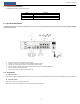
Introduction NVR User Manual 1.3 Front Panel Descriptions The following descriptions are for reference only. Name Descriptions REC When recording, the light is blue Net When access to network , the light is blue Power Power indicator, when connection , the light is blue 1.4 Rear Panel Descriptions To quickly get started, connect the following to your recorder in the following order, please refer to the following figure (N8NRL shown for reference). 1. 2. 3. 4. 5. 6.
Basic Operation Guide NVR User Manual 2 Basic Operation Guide 2.1 Startup & Shutdown Please make sure all the connections are done properly before you power on the unit. Proper startup and shutdown are crucial to expending the life of your device. 2.1.1 Startup ① Connect the output display device to the VGA/HDMI interface of the NVR. ② Connect with the mouse and power. The device will boot and the power LED would turn blue.
Basic Operation Guide NVR User Manual 2.3 Mouse Control Mouse control in Live Display & Playback interface In the live display & playback interface, double click on any camera window to show the window in single screen mode; double click the window again to restore it to the previous size. In the live display & playback interface, if the interfaces display in full screen, move the mouse to the bottom of the interface to pop up a tool bar.
EZ Setup & Main Interface NVR User Manual 3 EZ Setup & Main Interface 3.1 EZ Setup The disk icons will be shown on the top of the startup interface. You can view the number and status of each disk quickly and conveniently through these icons ( : no disk; : unavailable disk; : RW available disk). You can quickly configure the NVR by clicking “OK” to make the NVR work normally. You must configure the wizard if you start the NVR for the first time (or click “Skip” to cancel the EZ Setup next time).
EZ Setup & Main Interface NVR User Manual ③ Network Settings. Select the network work pattern as required. Check “Obtain an IP address automatically” and “Obtain DNS automatically” to get the IP address and DNS automatically (the DHCP function of the router in the same LAN should also be enabled), or manually enter them. Enter the HTTP port, RTSP port and Server port (please see 11.1.2 Port Configuration for details). Click “Next” to continue. ④ Other Network Settings.
EZ Setup & Main Interface be added to the corresponding channel. NVR User Manual To add cameras from the LAN, make sure all cameras are set to DHCP. of online IP cameras which are in the same local network with NVR and then click cameras in the list. Click Click “Refresh” to refresh the list to add the searched camera. Click “Add All” to add all the to delete the added camera. Click “Delete All” to delete all the added cameras. Click to edit the searched IP camera as shown on the below left.
EZ Setup & Main Interface NVR User Manual Manual: Set the “Sensor Record”, “Motion Record” and “Schedule Record” of each camera. Click “OK” to save. See 7.1.1 Mode Configuration for details. ⑧ QRCode. Enable the NAT function in the interface or set it in the network configuration after exiting the wizard (please refer to 11.1.7 NAT Configuration for details). You can scan the QRCode through the Speco Blue App available for iOS and Android to easily and securely view your cameras. Please refer to 12.
EZ Setup & Main Interface NVR User Manual Button Meaning Alarm status button. Click it to view the alarm status. Disk status button. Click it to view the disk status and RAID status. Network status button. Click it to view the network status. Information button. Click it to view system information. Introduction of area ②: Click “Camera” to view all the added cameras in the camera list.
EZ Setup & Main Interface NVR User Manual Here we take Camera module as an example. The Camera module provides convenient links such as “Add Camera”, “Edit Camera”, “Image Settings”, “Motion”, “Intelligence Analysis” and “PTZ”. Click Camera to go to the camera management interface as shown below. There are some function items on the left side of the camera management interface. Click each item to go to corresponding interface or window.
EZ Setup & Main Interface NVR User Manual Disk The module covers the functions such as Disk Management, Storage Mode and Disk Information and so on. Please see Chapter 7 Record & Disk Management for details. Network The module covers the functions such as TCP/IP, DDNS, Port, E-mail and Network Status and so on. Please see 11.1 Network Configuration for details. Account and Authority The module covers the functions such as Account Management (see 10.
Camera Management NVR User Manual 4 Camera Management 4.1 Add/Edit Camera 4.1.1 Add Camera The network of the NVR should be set before adding IP camera (see 11.1.1 TCP/IP Configuration for details). Refer to the pictures below. Click Add Camera in the setup panel or in the top right corner of the preview window to pop up the “Add Camera” window as shown below. You can quickly add or add the IP camera manually. Quickly Add Check the cameras and then click “Add” to add cameras.
Camera Management NVR User Manual effectiveness of the input information and then click “Add” button (you can input one camera’s information or above such as IP address, username and password before clicking “Add” button). Click of each camera. to delete the camera. Click “Default Password” to set the default username and password Note: Some models may not support this function. Click StartSettingsSystemBasicGeneral Settings to check “Enable Add IPC by Zero Operation”.
Camera Management NVR User Manual window if a batch of IPCs’ passwords need to be modified) and then click “Upgrade” button to start upgrading(the IPC will restart automatically after the upgrade is completed successfully). The IP cameras with PoE function which directly connect to the PoE port of the NVR will be displayed automatically in the camera list. Refer to the picture below. The IP camera which occupies the PoE resource has a prefix shown before its camera name.
Camera Management NVR User Manual 4.2.2 Edit Camera Group Click to modify the group information such as group name and dwell time. Click to delete the group. 4.2.3 IP Planning Some models may not support this function. Click “IP Planning” to go to the interface as shown below. This function supports searching other NVRs/DVRs that is in the same local network as the local NVR. The user may add camera channels of other NVRs/DVRs into the unoccupied channels of the local NVR.
Live View Introduction NVR User Manual 5 Live View Introduction 5.1 Live View Interface Introduction You should add camera first after logging on to the system (see 4.1.1 Add Camera for details). Refer to the interface as shown below, drag one camera in the preview window to another window for camera window exchanging.
Live View Introduction NVR User Manual 5.2 View Mode 5.2.1 Display Mode Set different screen modes and cameras’ display sequences as needed and then save the display modes classified by surveillance areas, priorities and so on. Refer to the picture below. Double click one display mode in the display mode list to view the live images in this mode. Add Display Mode Method One: ① Click “Customize Layout” in the above interface and then set the screen mode.
Live View Introduction NVR User Manual 5.2.2 Quick Sequence View You can start quick sequence view if the scheme has not been created. If the scheme has been created, please refer to 5.2.4 Scheme View in Sequence for details. Go to the live view interface and then click to pop up a little window. Set the dwell time in the window and then click to view the live group by group according to the camera number of the current screen mode.
Live View Introduction NVR User Manual ④ is the tool bar ( : clear button; : favorite button, click it to pop up a window, enter the display mode name in the window and then click “OK” to save the current display mode; other buttons are screen mode buttons). Click Add Scheme in area ① to create a new scheme. Click on the top right corner of the scheme to delete it.
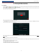
Live View Introduction NVR User Manual 5.3.2 Image Settings Click StartSettingsCameraImageImage Settings to go to the following interface. Select the camera and then set the brightness, contrast, saturation and hue of the camera. Click “Advanced” button or in the camera list on the right side of the interface to pop up “Image Adjust” interface and then set the relevant setting items. Please refer to 5.3.4 Image Adjustment for detailed introductions of these items.
Live View Introduction NVR User Manual Image Adjustment Select the camera and then click “Image Adjustment” to go to image adjustment tab. Refer to the above picture. Drag the slider to set the camera’s brightness, contrast, saturation and hue value. Check sharpen, wide dynamic and denoise and then drag the slider to set the value. Click “Default” button to set these parameters to default values.
Live View Introduction NVR User Manual The introductions of these parameters and buttons are as follows. Button/Parameter Meaning Click Focus Mode / to zoom in/out the image. If manual mode is selected, focus button & “One Key Focus” & “Day/night mode switch autofocus” will be available; if auto mode is selected, the time interval setup will be available. Click / to increase/decrease the focal length. Click it to focus instantly.
PTZ NVR User Manual 6 PTZ 6.1 PTZ Control Interface Introduction You can control the IP dome or PTZ which connects to the IP camera for PTZ control. Click on the tool bar at the bottom of the live view window to go to the PTZ control interface as shown below. You can select another IP dome or PTZ which connects to the IP camera on the top right of the interface for PTZ control. Introductions of the buttons on the bottom right of the interface: Button Meaning Click / / / to rotate the dome.
PTZ NVR User Manual Refer to the picture as shown below. Drag the mouse from C to D to get a green rectangle and the rectangle area will be zoomed out. Advanced 3D Control Double click the left button of the mouse on any area of the camera image and then the image size will be doubled and centered on the clicked point. Press and hold the left button of the mouse on any area of the camera image to zoom in the image; press and hold the right button to zoom out the image.
PTZ NVR User Manual then save the preset position after adjusting the dome’s direction); click in the preset list to call the preset; click “Delete” button to delete the selected preset. You can also go to preset setting interface for preset setting, see 6.2 Preset Setting for details. Cruise Setting Click “Cruise” to go to cruise operation tab and then click “Add” button to pop up a window as shown below left. You can add 8 cruises for each dome at most.
PTZ NVR User Manual Select camera and preset. You can enter the new name of the preset and then click to save the new preset name. Adjust the rotating speed, position, zoom, focus and iris of the preset and then click “Save Position” to save the preset. Delete Preset Select camera and preset and then click “Delete” to delete the preset. 6.3 Cruise Setting Click StartSettingsCameraPTZCruise to go to the interface as shown below.
Record & Disk Management NVR User Manual 7 Record & Disk Management 7.1 Record Configuration 7.1.1 Mode Configuration Please format the HDDs before recording (refer to 7.5 Disk Management for details). Click StartSettingsRecordMode Settings to go to the mode settings interface. You can set the record time under the “Manual Record Settings” and then click “Apply” button to save the settings. There are two record modes: auto mode and manual mode.
Record & Disk Management NVR User Manual Video Encode: the available options will be H.265 and H.264 if the connected IP camera supports H.265, or the option will be H.264 only. GOP: group of pictures. Resolution: the higher the resolution is, the clearer the image is. FPS: the higher the frame rate is, the more fluency the video is. However, more storage room will be taken up. Bitrate Type: CBR and VBR are optional.
Record & Disk Management NVR User Manual Click StartSettingsRecordStream Settings to go to “Sub-stream” interface. Set the encode, resolution, FPS, GOP, bitrate type, quality and max bitrate of sub-stream for each camera in the interface and then click “Apply” to save the settings. 7.3 Schedule Setting 7.3.1 Add Schedule Click StartSettingsRecordRecord ScheduleEdit Schedules to go to the interface as shown below.
Record & Disk Management Click area. NVR User Manual and then drag the cursor on the time scale to set record time; click and then drag the cursor on the time scale to delete the selected You can manually set the record start time and end time. Click or and then click “Manual” on each day to pop up a window as shown below. Set the start and end time in the window and then click “OK” to save the settings.
Record & Disk Management Go to “Edit Schedules” interface and then click Click NVR User Manual to edit the schedule. The settings of “Edit Schedule” are similar to that of the “Add Schedule”. to delete the schedule. 7.4 Record Mode 7.4.1 Manual Recording Method One: Click on the tool bar at the bottom of the live view interface to enable recording of the camera.
Record & Disk Management NVR User Manual Some models may not support this function. The settings of RAID are as followings. Please skip the settings of physical disk, array and disk mode if the NVR doesn’t support this function. Note: 1. The new HDD should be formatted for normal use. 2.
Record & Disk Management NVR User Manual 34
Playback & Backup NVR User Manual 8 Playback & Export 8.1 Instant Playback Click on the tool bar at the bottom of the preview camera window to play back the record (click on the tool bar at the bottom of the live view interface to set the default playback time). Refer to the picture below. Drag the playback progress bar to change the playback time. You can also click the right-click menu “Instant Playback” in the camera window and then set the instant playback time to play back the record. 8.
Playback & Backup NVR User Manual Button Meaning Full screen button. Click it to show full screen; click it again to exit the full screen. Screen mode button. OSD ON button. Click it to enable OSD; click to disable OSD. Stop button. Rewind button. Click it to play video backward. Play button. Click it to play video forward. Pause button. Deceleration button. Click it to decrease the playing speed. Acceleration button. Click it to increase the playing speed. Previous frame button.
Playback & Backup NVR User Manual Introduction of area ④: You can check the record type as required for record playback; first you should click the playback camera, then check the record type ( : manual record; on the tool bar at the bottom of the interface to clear all : sensor based record; : motion based record; : schedule record; in the playback window to add camera for playback (the record time scale will show the record data of : analytics record; and finally click the checked record type only
Playback & Backup NVR User Manual Note: If you back up the record in private format, the system will back up a RPAS player to USB device automatically. The private format record can be played by RPAS player only. ⑤ Click “Playback” button to play the record in the playback interface (refer to 8.2 Playback Interface Introduction for details). Click “Exit” to exit the interface. Time Slice Search: Method One: Click “Year”, “Month” or “Day” button under the record time scale to select the time slice mode.
Playback & Backup NVR User Manual 8.3.3 Time Search ① Click Start Search and ExportTime Search to go to the “Time Search” tab as shown below. ② Click on the bottom of the interface to add playback camera. A maximum of 16 cameras can be added for playback. Click “Modify” on the top right corner of the camera window to change the camera and click “Clear” to remove the camera. ③ Click the camera window to play the record in the small playback box on the left side of the interface.
Playback & Backup NVR User Manual ② Check the event type in the interface as required. ③ Click to set the start time and end time on the top left of the interface. ④ Check cameras on the left side of the interface or check “All” to select all the cameras and then click record will be displayed in the list. to search the record. The searched ⑤ Click in the list to play back the record in the popup window.
Playback & Backup NVR User Manual 8.3.7 View Export Status Click StartSearch and ExportExport Status or click on the tool bar at the bottom of the playback interface to view the export status.
Alarm Management NVR User Manual 9 Alarm Management 9.1 Sensor Alarm To complete the entire sensor alarm settings, you should enable the sensor alarm of each camera and then set up the alarm handling of each camera. ① Click StartSettingsAlarmSensor Alarm to go to the following interface. ② Select schedule and the alarm type (NO or NC) according to trigger type of the sensor. ③ Enable the sensor alarm of each camera.
Alarm Management NVR User Manual ② Select the camera, enable the motion and set the sensitivity and duration of the camera. Sensitivity: the higher the value is, the more sensitive it is to motion. You should adjust the value according to the practical conditions since the sensitivity is influenced by color and time (day or night). Duration: it refers to the interval time between the adjacent motion detections.
Alarm Management NVR User Manual ⑥ Click “Processing Mode” to go to the alarm handling configuration interface of object detection. Object Detection Alarm Handling Configuration: ① Click StartSettingsAlarmIntelligence AlarmObject Detection to go to the following interface. ② Enable or disable “Snapshot”, “Push”, “Alarm-out”, “Preset”, “Buzzer”, “Pop-up Video” and “E-mail”. The alarm handling setting of object detection alarm is similar to that of the sensor alarm (see 9.1 Sensor Alarm for details).
Alarm Management NVR User Manual ② Select the camera and enable the relevant detection as needed. Scene Change: Alarms will be triggered if the scene of the monitor video has changed. Video Blurred: Alarms will be triggered if the video becomes blurry. Video Color Cast: Alarms will be triggered if the video becomes obscured. ③ Set the sensitivity of the exception detection. ④ Click “Apply” to save the settings.
Alarm Management NVR User Manual ② Select the camera, enable the line crossing detection. ③ Select the direction. Direction: A<->B, A->B and A<-B optional. It is the crossing direction of the intruder who crosses over the alert line. A<->B: the alarm triggers when the intruder crosses over the alert line from B to A or from A to B. A->B: the alarm triggers when the intruder crosses over the alert line from A to B. A<-B: the alarm triggers when the intruder crosses over the alert line from B to A.
Alarm Management NVR User Manual ⑤ Click “Apply” to save the settings. ⑥ Click “Processing Mode” to go to the alarm handling configuration interface of intrusion detection. Intrusion Detection Alarm Handling Configuration: ① Click StartSettingsAlarmIntelligence AlarmIntrusion to go to the following interface. ② Enable or disable “Snapshot”, “Push”, “Alarm-out”, “Preset”, “Buzzer”, “Pop-up Video” and “E-mail”.
Alarm Management NVR User Manual 9.4.2 Warning Handling Settings ① Click StartSettingsAlarmExceptionWarning Handling Settings to go to the interface as shown below. ② Enable or disable “Push”, “Alarm-out”, “Buzzer”, “Pop-up Message Box” and “E-mail”. The exception handling settings are similar to that of the sensor alarm (see 9.1 Sensor Alarm for details). ③ Click “Apply” to save the settings. 9.5 Alarm Event Notification 9.5.
Alarm Management NVR User Manual and the pop-up message box. Click “Apply” to save the settings. 9.5.4 Buzzer Click StartSettingsAlarmEvent NotificationBuzzer to go to the buzzer configuration interface. Set the delay time of the buzzer and then click “Apply” to save the setting. You can click “Test” to test the buzzer. 9.5.5 Push Message Click StartSettingsAlarmEvent NotificationPush Message to go to the interface as shown below.
Alarm Management NVR User Manual Click “Clear” button to stop the buzzer when the buzzer alarm happens. Click to view the detail information as shown below. If the exception information is more than one page, you can enter the number in the box and then click / to view the exception alarm information in the previous/next page. Click 50 to jump to the specified page. Click to play the alarm record.
Account & Permission Management NVR User Manual 10 Account & Permission Management 10.1 Account Management Click StartSettingsAccount and AuthorityAccountEdit User to go to the interface as shown below. Area ① displays the user permissions. Area ② displays the user list. Click the user in the list to display its user permissions in area ①. There are three default permission groups (“Administrator”, “Advanced” and “Common”) available when adding accounts.
Account & Permission Management NVR User Manual Edit Security Question You can set password security only for admin. Click “Edit Security Question” and then set questions and answers in the popup window. If you forget the password for admin, please refer to Q4 in Appendix A FAQ for details. The passwords of other users can be recovered by admin or the users that have the “Account and Authority” permission. Modify Password Only the password of admin can be modified.
Account & Permission Management NVR User Manual to log out the system. 10.3 Permission Management 10.3.1 Add Permission Group Click StartSettingsAccount and AuthorityAccountEdit Permission Group to go to the interface as shown below. Click to add permission group. Set the group name, check the permissions as needed and then set the “Local” and “Remote” permissions. Click “Add” to save the settings. 10.3.
Account & Permission Management NVR User Manual ② Check “Enable” and then choose “Enable Allow List” or “Enable Block List” (the PC client of which the IP address is in the allow list can access NVR remotely while the PC client in the block list cannot). ③ Add IP/IP segment/MAC. Click “Add IP” or “Add MAC” button and then check “Enable” in the popup window (only if you check it can the IP/IP segment/MAC you add be effective). Enter the IP/IP segment/MAC and then click “OK” button.
Device Management NVR User Manual 11 Device Management 11.1 Network Configuration 11.1.1 TCP/IP Configuration Click StartSettingsNetworkTCP/IP to go to the following interface. Check “Obtain an IPv4 address automatically”, “Obtain an IPv6 address automatically” and “Obtain DNS automatically” to get the network addresses automatically, or manually enter the network addresses.
Device Management NVR User Manual stream protocol, you can view the live images synchronously. The default RTSP port is 554 and it can be changed as required. Note: The HTTP port and server port of the NVR should be mapped to the router before you access the NVR via WAN. 11.1.3 PPPoE Configuration Click StartSettingsNetworkPPPoE to go to the interface as shown below. Check “Enable” in “PPPoE Settings” and then enter the username and password obtained from the dealer.
Device Management NVR User Manual Click “Edit Recipient” to go to the following interface. Click “Add” and then enter the recipient’s e-mail address and select the schedule (if a schedule is selected, the system will send the alarm email and the recipient will receive it only in the selected schedule time) in the popup window. Click “Add” in the window to add the recipient. You can also change the recipient’s receiving schedule by clicking in the “Schedule” column. Click save the settings.
Device Management NVR User Manual 11.1.7 NAT Configuration Click StartSettingsNetworkNAT to go to the interface for NAT configuration and check “Enable”. Click “Apply” to save the settings and make note of the QR code number under the QR code. Via Internet Explorer, go to connect.specotech.cloud, input the QR code number, your username and password to login. You can also scan the QRCode through mobile client which is installed in the mobile phone or PAD to log in the mobile client instantly. 11.1.
Device Management NVR User Manual You can manually set the system time or synchronize system time with network through NTP. Manual: select “Manual” in the “Synchronous” option and then click after the “System Time” option to set the system time. NTP: select “NTP” in the “Synchronous” option and then enter the NTP server. 11.
Device Management NVR User Manual 11.5 Backup and Restore You can back up the configuration file of the NVR by exporting the file to other storage devices; you can recover the configuration to other NVRs which are of the same model with the NVR by importing the configuration file to other NVRs for time saving. Insert the USB storage device into the USB interface of the NVR and then click StartSettingsSystemMaintenanceBackup and Restore to go to the interface.
Device Management NVR User Manual Choose the log file in the list and then click “Export” button to export the log file. Click contents in the menu list and then the log list will show the checked log contents only. Click on the “Content” title bar to pop up a menu list. Check to play the video log. 11.
Remote Surveillance NVR User Manual 12 Remote Surveillance 12.1 Mobile Client Surveillance ① Enable NAT in the NVR. Refer to 11.1.7 NAT Configuration for details. ② Scan the QRCode through the Speco Blue App available for iOS and Android to easily and securely view your cameras. ③ Run the mobile client, go to the “Add Device” interface and then click to scan the QRCode of the NVR (Go to StartSettingsSystemInformationBasic to view the QRCode of the NVR).
Remote Surveillance NVR User Manual ② Click Start→Settings→Network→NAT to go to the interface for NAT configuration and check “Enable”. Click “Apply” to save the settings and make note of the QR code number under the QR code. Via Internet Explorer, go to connect.specotech.cloud, input the QR code number, your username and password to login. PPPoE Access ① Click StartSettingsNetworkPPPoE to go to the “PPPoE” interface.
Remote Surveillance NVR User Manual Start Preview Select a window in the preview area and then click one online camera on the left panel to preview the camera in the window. You can click the tool bar to view all the cameras. Left Panel Introduction Click on the left panel to hide the panel and click View Camera Click on the left panel stands for the number of online cameras; the right number 4 stands for the number of all the added cameras.
Remote Surveillance Click NVR User Manual to go to “Lens Control”. Click to go to “Operation” panel. Click one camera window in the preview area and then click to set the camera’s live view stream and record stream to main stream in manual record mode; click to set the camera’s live view stream and record stream to sub stream. In sub stream tab, set the resolution, FPS and bitrate and then click “Apply” to save the settings. Operation panel introduction: Button Meaning Click it to take snapshots.
Remote Surveillance NVR User Manual Button Meaning Click it to view the cruise list and then click the corresponding buttons in the list to start or stop the cruise. 12.4.2 Remote Playback Click “Playback” in the remote interface to go to the playback interface. ① Check the record event types and cameras on the left panel. Set the record date on the calendar beside the time scale. ② Click to search the record data and then click or directly click the time scale to play the record.
FAQ NVR User Manual 67
FAQ NVR User Manual Appendix A FAQ Q1. Why can’t I find the HDD? a. Please check the power and SATA data cables of the HDD to make sure they are well connected. b. For some NVRs with the 1U or small 1U case, the power of the adapter may be not enough for operating them. Please use the power adaptor supplied along with the NVR. c. Please make sure the HDDs are compatible with the NVR. See Appendix C Compatible Device List for details. d. The HDD could have gone bad. Change a new one. Q2.
FAQ NVR User Manual connecting the IP cameras directly. In this situation, if you directly connect one IP camera to PoE5, PoE6, PoE7 or PoE8, the IP camera will be displayed in the camera list automatically; if you connect it to PoE1, PoE2, PoE3 or PoE4, it won’t be displayed in the camera list by showing resource conflict; if you just need to connect it to PoE1, PoE2, PoE3 or PoE4, you should first delete the IP camera which occupies the PoE port resource and then reconnect it to the PoE port.
FAQ NVR User Manual cannot access the NVR remotely. Q10. a. ActiveX control cannot be downloaded. How can I do? IE browser blocks ActiveX control. Please do setup as per the steps mentioned below. ① Open IE browser. Click Internet Options. ② Select SecurityCustom Level. Refer to Fig 10-1. ③ Enable all the sub options under “ActiveX controls and plug-ins”. Refer to Fig 10-2. ④ Then click “OK” to finish setup. b. Other plug-ins or anti-virus may block ActiveX.
FAQ NVR User Manual format. b. Record backed up through web. The record can only be backed up with AVI format through web. The record can be backed up to PC and played by the video player which supports this format.
Calculate Recording Capacity NVR User Manual Appendix B Calculate Recording Capacity The recording capacity is mainly up to the record resolution, record stream and bitrate. Different image quality parameters decide different disk capacity occupation in equal times. The bigger the record resolution, record stream and record bitrate is, the more disk capacity is taken up in equal times. The calculation format of recording capacity is shown as below.
Compatible Device List NVR User Manual Appendix C Specifications Model System Video N8NRL Compression OS Embedded Linux IPC Input Network Bandwidth Network Format 8CH 4CH 50Mbps 40Mbps Access Access Record Playback Network Input 2-way Audio RCA×1 Local Output RCA×1 Record Stream Dual stream recording Resolution 8MP/5MP/4MP/3MP/1080P/960P/720P Mode Simultaneous Playback Manual, schedule, motion, sensor, intelligence Search Mode Smart Search Function Alarm Network Mobile Device Stora